4.6.2. Interface details
Refer to sections 4.6.3.1 to 4.6.3.9 for connection details for P1 to P8 on the
e
-Brick;
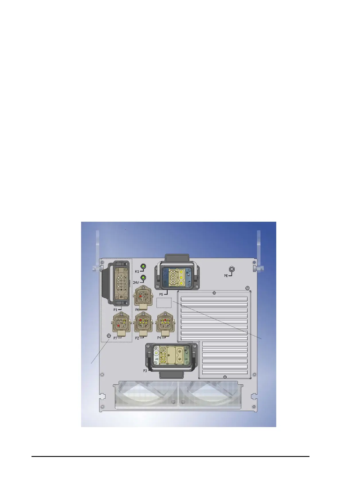
Figure 7 shows the positions of the connectors on the rear panel for the 9/12kW products.
Connectors are arranged differently for the 22kW
e
-Brick, refer to Figure 7(a,b). P1, P2,
P4, P6, P7, P8 are identical; P5 (Power input) and P3 (Lamp output) are functionally identical
but have larger connectors and terminal inserts to handle higher voltages and currents.
Please note the following:
Note! These connections apply to
e
-Brick products 26365 & 26366 (12kW), 26602,
26603, 26367, 26368 & 26391 (9kW), 25158, 26790, 33276 & 33485 (22kW) and derivatives
of these models. Refer to issue 1.0 of this manual for connection details of 23326 & 23329
(12kW), 24101, 24104 & 26376 (9kW).
Warning! Where ‘Volt free’ outputs are specified, the maximum contact rating of the
internal relay contact is provided in the tables below; if this rating is exceeded contact
damage may occur and the GEW warranty will be void.
Warning! To ensure isolation of the
e
-Brick from external systems, where a ‘Volt free’
contact input is specified the externally connected equipment should be interfaced by a relay
capable of switching 24Vdc at <0.5A. Applying voltages to these inputs may cause serious
damage to the
e
-Brick and invalidate the GEW warranty.
P8
P8 only fitted
on Profibus
master e-brick
P1 & P7
not fitted
on slave
Figure 7: Rear panel (Master) connection details
GEW UV
e
-Brick installation and operating manual 23 of 49