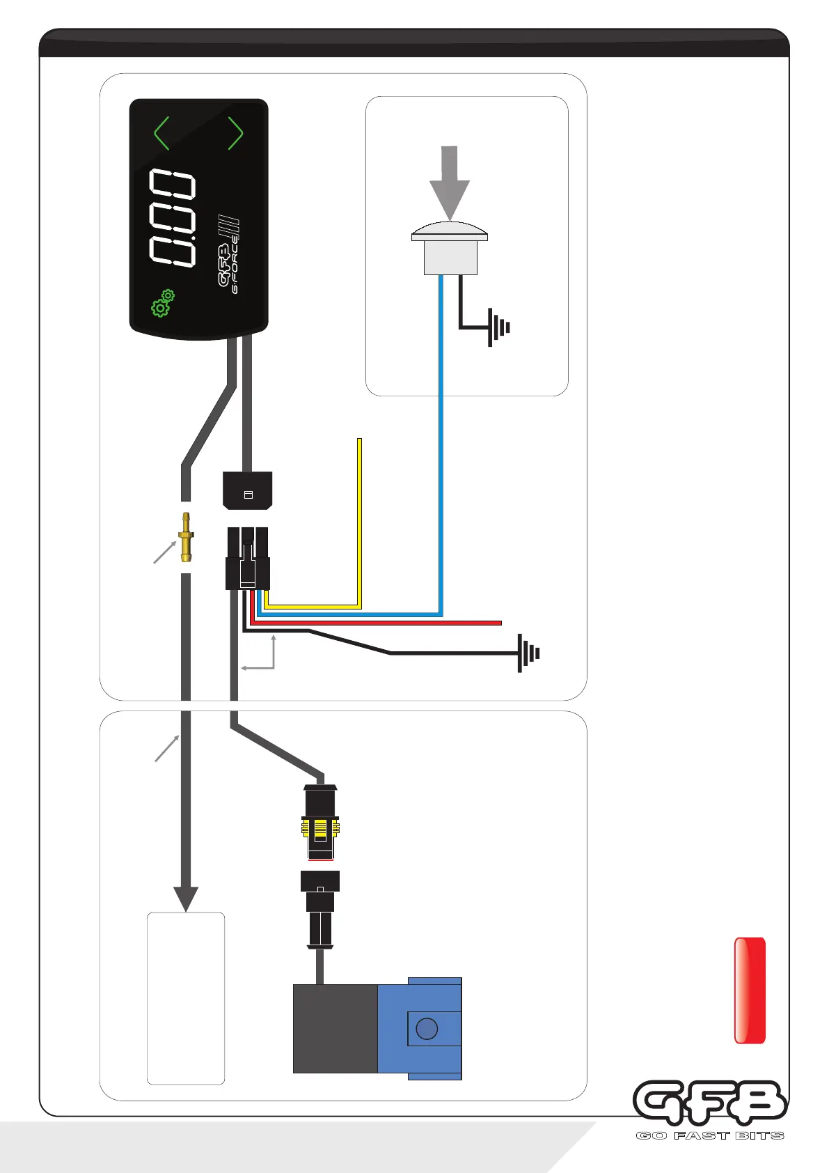
To intake manifold -
use small Tee to tap into
an existing vacuum hose
if necessary
1/8” I.D. vacuum hose
Vacuum hose joiner
Loom
3-Port Boost
Control Solenoid
Black wire -
Vehicle ground (chassis)
Red wire -
+12V switched power source.
It is recommended to connect
via a 5A fuse (not supplied)
Blue wire - Input 1
(see notes below, and
pages 14 & 17 for details)
Optional Remote Trigger Circuit
Engine Bay
Vehicle Interior
Yellow wire - Input 2
(Connect to Wideband module for AFR
display. See notes below for details)
Remote trigger button (not
supplied). Use any switch, button
or sensor that grounds the blue
wire when activated
Input 1 (blue wire) can be used as a remote trigger simply by connecting it to any kind of switch, button, or programmable ECU output that
grounds the blue wire to the vehicle earth when activated. For ideas on different ways to use this feature, see page 17. Once connected, the
function of Input 1 must be configured within the “In.1” sub-menu (see page 14).
Input 2 (yellow wire) may be connected to an external Wideband O2 control module/sensor (not supplied). Connect the yellow wire directly to
your wideband controller’s auxiliary 0-5V analogue output, then configure using the “In.2" sub-menu (see page 14).
If either the blue or yellow wire are not used, simply cut or bundle them and make sure they are insulated.
WARNING!
DO NOT connect the blue or yellow wire to a 12V source as this could damage the unit.
3 - installation
wiring diagram
SETTINGS
PRESET
SCRAMBLE
(4-port solenoid available
separately. GFB Part # 3845)