Port 2
Port 3
Wastegate
actuator
Turbo
Boost pressure
source
You can prevent dirt from getting into the factory solenoid whilst it is not in use by simply connecting its inlet and
outlet together with a short loop of hose.
The G-Force III solenoid should be mounted in a position away from significant heat sources (such as the exhaust
manifold and turbine), and where it is protected from rain or splashed water. The unused outlet of the solenoid
valve should be positioned in a way to prevent ingress of dust, dirt and water.
DO NOT plug the unused solenoid port, as this will prevent the controller from being able to adjust boost pressure.
Port 2
Port 1
Wastegate
Turbo
Boost pressure
source
Top port
Bottom port
Large Tee
Screw the two supplied hose
tails into ports 2 and 3 of the
solenoid valve, and connect
the ports to the correct
locations as shown using the
supplied 3/16” hose.
Screw the two supplied hose
tails into ports 1 and 2 of the
solenoid valve, and connect
the ports to the correct
locations as shown using the
supplied 3/16” hose.
4 - installation
solenoid valve installation
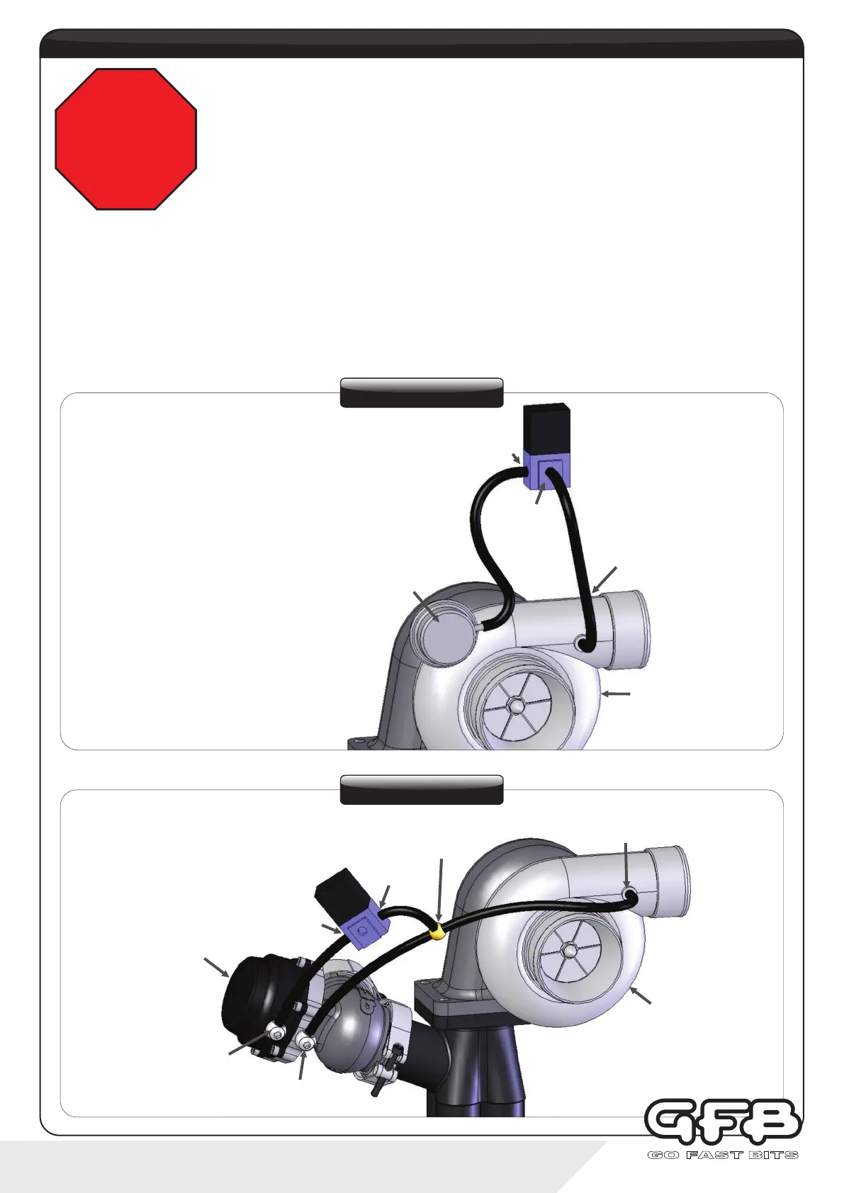
STOP
PLEASE READ before installing the G-Force III on a vehicle that has an
existing factory boost control solenoid.
The G-Force III is designed to work as a stand-alone boost controller, therefore any existing
factory-fitted boost control devices must be removed or disabled.
However, disconnecting a factory-fitted solenoid valve from the car’s wiring loom may cause
an ECU error code and/or a Check Engine warning light. To prevent this, leave the factory
solenoid in place with the electrical wires connected, but remove the vacuum/boost hoses.
External Wastegate
Internal Wastegate