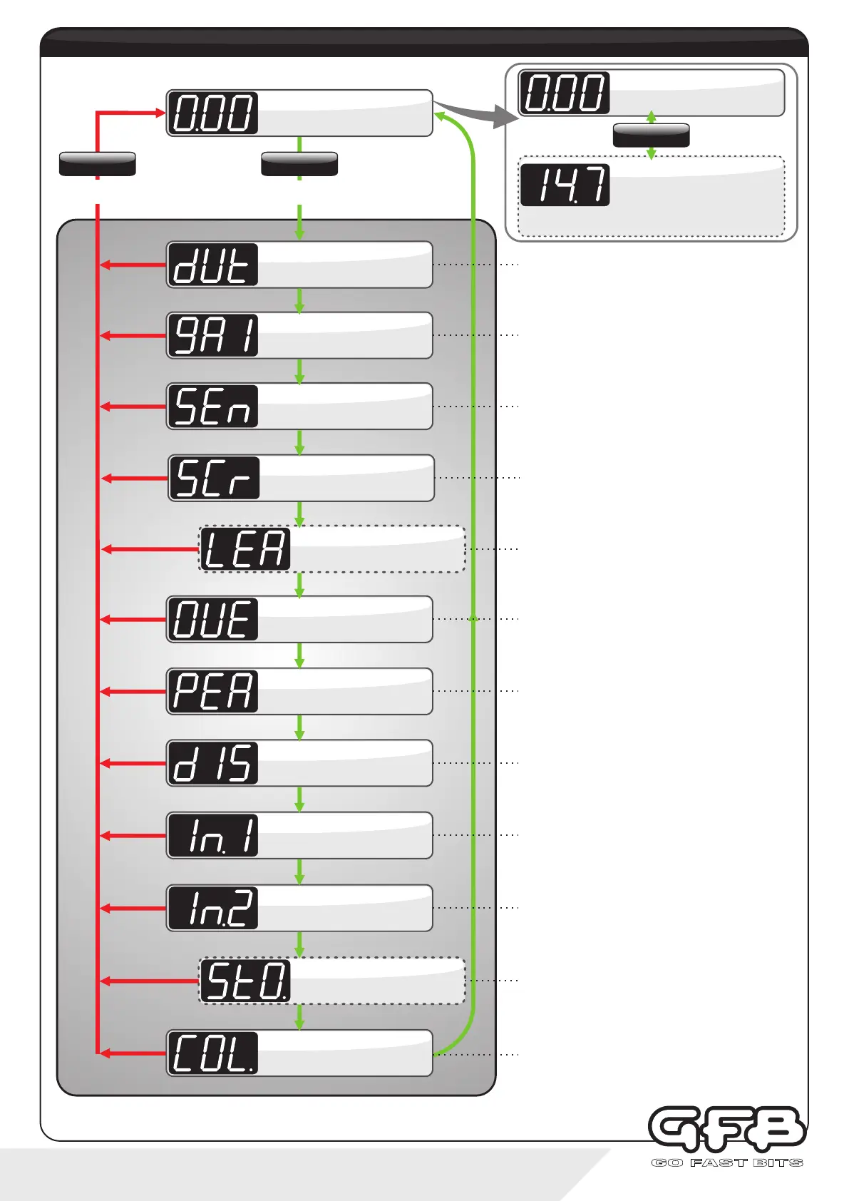
5 - Menu navigation
Allows changes to the button illumination colours.
The display does not change, but pressing “up” will alter
the “scramble/preset active” button colour, and pressing
down” will alter the normal “background” button colour.
Display shows “COL.”.
For more details, see page 16.
Button Colours
RUNNING MODE
Controls peak boost pressure.
Duty Cycle is adjustable from 10-100%, where 10 results
in the lowest boost pressure, and 100 is the highest.
Display scrolls “dUtY”, followed
by “PEAK”. Details see page 8.
Duty Cycle
Controls how fast the turbo spools up.
Gain is adjustable from 0-100, where 0 is the slowest
spool-up, and 100 is the fastest.
Display scrolls “gAIn”.
For more details, see page 9.
Gain
Controls how strongly the G-Force III attempts to correct
changes in boost pressure. Sensitivity is adjustable from
0-100, where 0 results in no correction and, and 100 is the
strongest.
Display scrolls “SEnS”.
For more details, see page 10.
Sensitivity
Sets the number of seconds that the scramble boost
feature remains on when activated.
Adjustable from 0-100 seconds.
Display scrolls “SCr SEC”.
For more details, see page 11.
Scramble Seconds
Turns off the solenoid in the case of over boost.
The Overboost setting is adjustable from 0-345kPa, 0-
3.45bar, or 0-50psi, depending on which display units are
currently in use.
Display scrolls “OVErbSt”.
For more details, see page 12.
Overboost
Turns the Peak Hold display function on and off.
When set to “ON”, the display briefly shows the last peak
boost value after the manifold drops to vacuum.
Display scrolls “PEAK”.
For more details, see page 13.
Peak Hold
Changes the display pressure units.
Can be set to kPa (default setting), BAR, or PSI.
Display scrolls “dISP”.
For more details, see page 13.
Display Units
Changes the function of the blue input wire.
“OFF” turns off the remote input, “PrE” jumps to the next
boost preset, and “SCr” activates scramble feature.
Display shows “In.1”.
For more details, see page 14.
Input 1 Setup
To exit from the
menu at any point
To enter menu and advance
through the options
menu structure
(Normal controller operation)
This sub-menu is only visible if “In.2" is configured. It sets
the AFR or Lambda value which will turn off the boost
control solenoid if the engine runs too lean. Adjustable
between 3.2:1 and 25.5:1 AFR, and 0.50-1.50 Lambda.
Display shows “LEA”.
For more details, see page 12.
Lean Cut
Configures G-Force III to suit the wideband O2 controller
being used, and whether the display shows AFR or
Lambda. Can be set to OFF, AF1, AF2, AF3, λ1, λ2 or λ3.
Please refer to page 14 for detailed setup.
Display shows “In.2”.
For more details, see page 14.
Input 2 Setup
Sets the Stoichiometric value of the air/fuel ratio for the
fuel type being used. Note that this sub-menu will only be
visible if AF1, AF2 or AF3 is selected in “In.2” above.
Adjustable between 6.0:1-18:1, see page 15 for setup.
Display shows “StO.”.
For more details, see page 15.
Stoich. Fuel Ratio
AFR DISPLAY*
BOOST DISPLAY
Displays boost pressure
SETTINGS
Hold
To toggle display
SETTINGS
Tap
SETTINGS
Hold
Di sp lays AF R or Lambd a.
Displays 3 dashes when sensor
is out of range
(*Only enabled when a Wideband Controller is connected to
Input 2).