23
4. Remove the earth wire、live wire and neutral wire.
5. Attach the mains cable wires to the terminal block on the power PCB, and attach the new cable tie.
Cord type Live wire Neutral wire Earth wire
USA/ JAPAN
(115/ 100 V)
Black or
Brown
White or
Blue
Green or
Green/Yellow
EUROPEAN
(230V)
Brown Blue Green/Yellow
NZ/ AUSTRALIA
(230 V)
Brown Blue Green/Yellow
Caution:When attaching the mains cable wires, ensure that the correct polarity of the mains wiring is
followed. The table given above only applies to power cords supplied by Great Group Medical Co., Ltd.
6. To fixed the power cord.
7. Close the case.
6.2.5. Replacement of Printed Circuit Boards (PCBs)
1. Open the case.
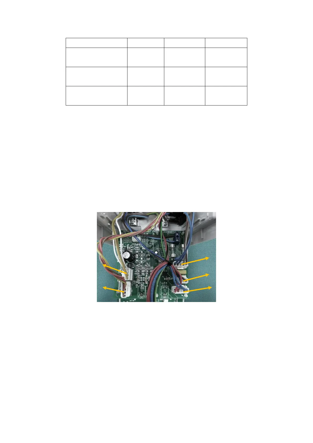
2. Disconnect all harnesses attached to the power PCB. Disconnect the mains and protective earth wires by
unscrewing the terminal blocks, and cutting the cable ties.
3. Remove the power PCB and replacement the new one.
4. Connect harnesses from the transformer and heater plate to the power PCB.
5. Close the case.
6. Check that the unit powers up normally, and complete a full performance test.
6.2.6. Replacing the Termistor.
1. Open the case.
2. Disconnect the mica cable, thermistor and thermal cutout harnesses attached to the power PCB.
3. Remove the three screws holding the heater plate.
 Loading...