25
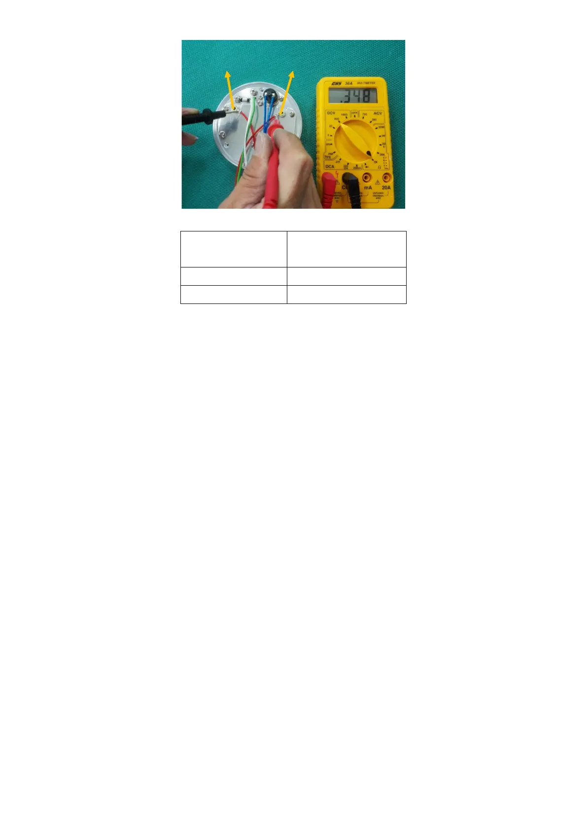
The resistance of the heater plate element should measure the same as outlined in the table below:
Supply Voltage
Heater Plate
Resistance
230V 353.0 ± 18.0 Ω
115V 88.0 ± 4.0 Ω
If the measured resistance is outside this range, replace the mica.
5. Remove the six screws holding the mica.
6. Remove the heater element, leaving the mica insulator in place.
7. Attach the six screws holding fixed plate.
8. Place the heater plate assembly back into position, ensuring the springs underneath the heater plate are in
place. Attach to the humidifier case using the three long screws that were previously removed.
9. Connect the heater plate element, thermistor and thermal cutout harnesses to the power PCB.
10. Close the case.
6.2.8. Replacing the Thermal Cutout
1. Open the case
2. Disconnect the mica cable, thermistor and thermal cutout harnesses from the power PCB.
3. Remove the three screws holding the heater plate.
4. Remove the two screws holding the thermal cutout.
5. Place new thermal cutout in position and fasten using screws provided.
6. Attach the screws holding.
7. Place heater plate back into position, ensuring the springs underneath the heater plate are in place. Attach
to the humidifier's case using the three long screws that were previously removed.
8. Connect the mica cable, thermistor and thermal cutout harnesses to the power PCB.
6.2.9. Closing the Case
1. Make sure that all harnesses that were previously disconnected have been reconnected. If the mains
wiring was disconnected during servicing, check that the mains polarity is correct.
2. Slide the power PCB back into position, ensuring that the side panel slides in the slots and latches into
the case rear.
3. Place the control PCB back into position in the front of the case, ensuring all clips are located properly.
4. Slide the case together, and replace the four screws.
 Loading...