B
Brooke MillerSep 23, 2025
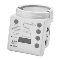
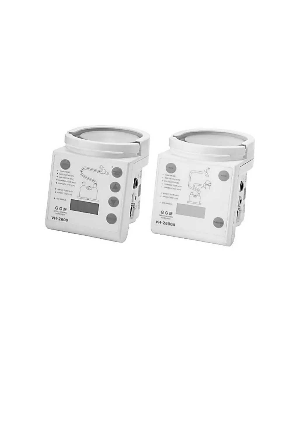
Why is the temperature less than desired on my GGM Humidifier?
- RRichard LaneSep 23, 2025
If the temperature is less than desired on your GGM Humidifier and there is no alarm, the humidifier may be in the process of warming up. Wait for a few minutes to see if the temperature reaches the desired level.