SV200 R200
4/2007© by GLOBAL GARDEN PRODUCTS
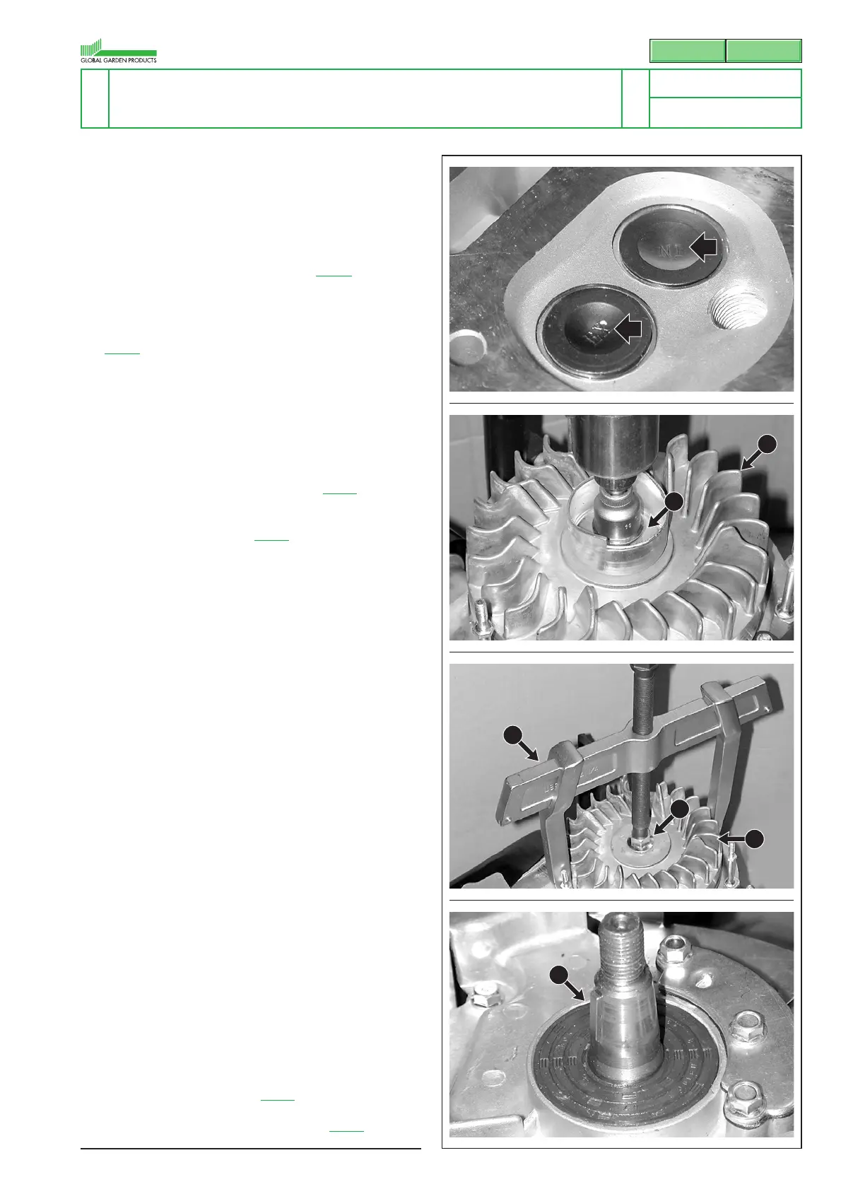
– apply a film of oil on the valve stems before
inserting them in their respective housings;
– ensure the correct position of the inlet valve
and the exhaust valve, marked, respectively,
with «IN» and «EX» on the valve head.
52 Remount the cylinder head [
6.9.C].
53 The valve clearances must be checked whenev-
er the cylinder head is removed and refitted [
6.9.B
].
E) Dismantling and replacing the magneto
flywheel
61 Remove the starting system [ 6.2.A].
62 Remove the tank [
6.1.A].
63 Remove the conveyor (20).
NOTE - If no tools are available for locking rota-
tion of the engine shaft, a striker gun must be
used for removing and refitting the flywheel.
64 Use a striker gun to unscrew the nut (41) locking
the magneto flywheel (42).
65 Screw the nut (41) a few turns onto the engine
shaft so that the puller is not working directly on
the shaft.
66 Remove the magneto flywheel (42) using a puller
(43) suitable for the purpose.
67 On assembly check the condition of the spline
key (44) and replace it if damaged; screw on the
nut (41) to the specified torque using a striker
gun.
68 Remount the conveyor (20).
35 Remount the tank [
6.1.A].
36 Remount the starting system [
6.2.A].
6.9.1
ENGINE BLOCK – External operations
5 / 7
SERVICE MANUAL
page
from
2007 to ••••
44
41
42
41
43
42
 Loading...