57
PUSHTOOPEN
©Ghost Controls
®
2020
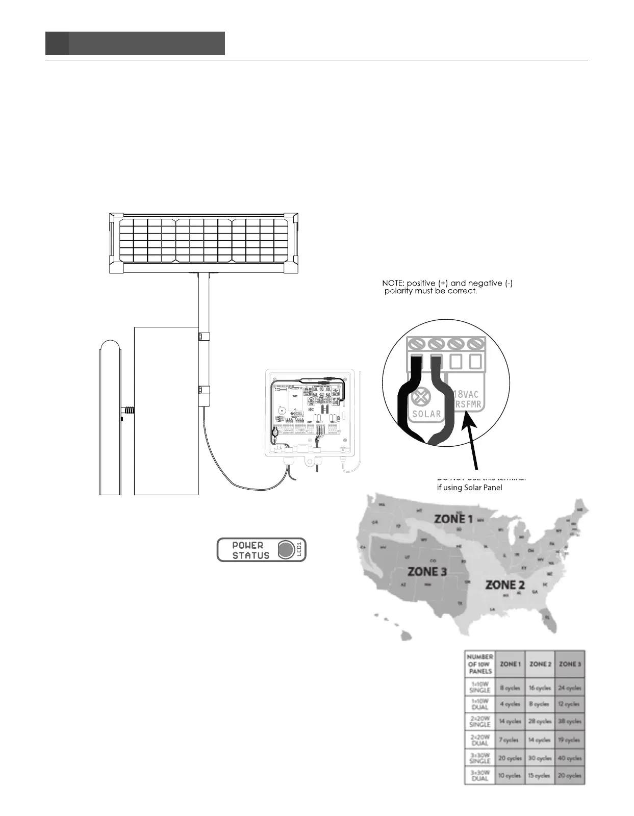
CONNECTING SOLAR TO YOUR SYSTEM
STEP 22. Adding a solar panel (optional) to the control box. Turn your system o
A. When wiring a Solar Panel you will need to insert the two solar wires into the SOLAR SCREW TERMINALS
which are located on the PWR INPUT section of the main control board. Once inserted then tighten each
screw so that the wires do not come loose and fall out. Please refer to diagram below. DO NOT CONNECT
AC TRANSFORMER IF USING SOLAR POWER.
DO NOT USE this terminal
if using Solar Panel
Black
Red
Battery Harness
Operator Arm
Connect the Solar Wire’s to the
control board “Solar” terminals.
Connect the red wire to the
positive (+) “SOLAR” terminal
and the black wire connects to
the negative (-) “Solar” terminal
on the control board.
B. Turn the system on. Check that green LED (Power status)
on top center of control board is on. This indicates that
the battery is being charged.
C. Check the chart shown for number of hours of direct
sunlight available for solar applications.
D. Determine the number of expected winter cycles for a
single gate using solar power by reviewing the map and
chart shown.
A MAXIMUM OF 3 AXDP 10WATT SOLAR PANELS OR NO
MORE THAN 30WATTS OF SOLAR POWER SHOULD BE
CONNECTED TO ANY GHOST CONTROLS SYSTEM
CONTROL BOARD.