Do you have a question about the Ghost Controls Ghost Pro Series and is the answer not in the manual?
Ghost Controls main address and website information for customer inquiries.
Contact details for sales, product information, and retailer location services.
Phone number and hours for technical support and installation assistance.
Links to technical support articles and installation videos on the website.
Lists essential items and considerations before starting the gate opener installation.
Information on additional accessories for gate customization and where to find details.
Instructions and form for registering the product to get an extended warranty.
Website address for online warranty registration.
Details for filling out and mailing the warranty form if internet access is unavailable.
Fields to provide details about the gate type, weight, length, and application.
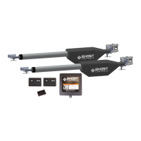
Detailed technical specifications for the LDM2 gate operator kit.
Chart showing maximum gate length and weight supported by the LDM2 operator.
Important safety precautions and warnings for installers and users of the gate opener system.
Guidance on identifying and avoiding potential entrapment areas during gate operation.
Safety guidelines for installation, operation, and regular maintenance of the gate opener.
Requirement to attach warning signs and user awareness for safe gate operation.
Recommendation to follow ASTM F2200 for vehicular gate construction and installation.
Instructions on where and how to install warning signs for gate safety.
Explanation of the gate opener's audible alarm and its triggers.
A caution to exercise extreme care when the automatic gate opener is in operation.
Visual representation of potential entrapment areas around the gate operator system.
Detailed notes on specific entrapment areas and associated risks.
Key instructions and guidelines for using the Ghost Controls gate opener system.
Criteria the gate must meet for proper installation and operation of the opener.
Information on the SafeForce® feature and the use of external safety devices like photo eyes.
Emphasizes the necessity of a separate gate for pedestrian access.
Instructions on trenching and using conduit for dual gate power cables.
Illustrates and describes the two main gate swing directions for installation.
Warning against using vehicle sensors on properties with livestock or animals.
Key considerations for preparing the gate and site before installing the operator.
Ensures the gate swings freely, is plumb, and level without dragging.
Guidelines for securely mounting gates to concrete-secured posts for stability.
Specifies the need for an accessory Push-To-Open bracket kit for specific installations.
Considerations for mounting locations of the control box, battery box, and operator arm.
Explains choices between AC transformer and solar power for battery recharging.
Details on the type and length of low voltage wire needed for AC transformer and solar panel connections.
Methods for triggering gate opening, such as push buttons or transmitters.
Discusses different mounting locations for the operator on the gate and their implications.
Explains the criticality of proper rear bracket positioning for leverage and clearance.
Directs users to specific pages for Pull-To-Open and Push-To-Open installations.
Lists the necessary tools for installing the gate opener system.
Details the hardware components for post and rear mounting of the operator.
Lists the hardware components for attaching the operator to the gate.
Components for mounting the control box, including screws and cable ties.
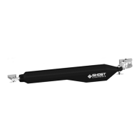
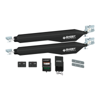
Identification of the operator arm and the included 5-button remote transmitter.
Lists the hardware components specific to installing a second gate operator.
Identifies the positive stop gate bracket and associated hardware.
Introduces the operator arm installation for Pull-To-Open gates.
Explains that the gate swings into the property for Pull-To-Open installations.
Important notes regarding the non-use of wheels and recommendations for heavy gates.
First step involves establishing and marking center lines for gate bracket alignment.
Instructions for assembling the post bracket with pivot brackets and hardware.
Securing the pre-assembled post bracket to the post using the marked centerline.
Recommendation for notching round wooden posts for proper post bracket installation.
Information on optional adapter accessories for round steel posts.
Ensuring 4" gate clearance and completing the rear post mount bracket assembly.
Drilling holes and securely bolting the rear post bracket to the post.
Attaching the operator to the secured rear post mount using clevis pin and hairpin.
Deciding where to mount the control and battery boxes, ensuring proximity.
Pre-drilling holes and securing the control and battery boxes to the fence.
Ensuring the on/off switch on the control box is in the off position before proceeding.
Routing the battery harness through the strain relief and connecting to the control board.
Connecting the battery harness terminal leads to the system's battery.
Emphasizing the requirement of a battery for system operation.
Correctly connecting the red wire to positive (+) and black wire to negative (-) battery terminals.
Routing the operator cable through the strain relief into the control box.
Connecting the operator wires to the color-coded terminals on the control board.
Ensuring wires are properly inserted and insulation doesn't impede contact with the control board.
Recommending a padlock for the control box to prevent tampering.
Verifying the system's DIP switch settings are in the correct positions.
Configuring DIP Switch 1 to set the gate's opening direction (Pull-to-Open or Push-to-Open).
Setting DIP Switch 2 to enable or disable the warning alarm for AUTOCLOSE and initial gate movement.
Setting DIP Switch 3 for SafeForce® Mode or Monitored Safety Devices.
Configuring DIP Switch 4 for dual gate opening sequences (delay or simultaneous).
Using jog buttons to test the operator arm and connections after turning on the control box.
Using the remote transmitter to fully retract the arm to set the OPEN position.
Warning against screwing the operator arm in or out to adjust gate position.
Temporarily assembling the front mount bracket to the gate bracket.
Information on alternate tube gate brackets for tubular gates.
Lining up and marking the gate bracket mounting holes on the gate.
Ensuring the gate is in the desired OPEN position for bracket mounting.
Securing the front mount and estate brackets to the gate with hardware.
Marking and drilling the innermost hole on the front mount bracket for attachment.
Aligning and tightening the brackets to the gate securely.
Aligning and attaching the operator arm to the secured front mount bracket.
Instructions to repeat installation steps for adding a second gate operator.
Installing the supplied positive stop plate on the inside of the first operator gate.
Moving on to programming the closed limit switch.
Key notes on adjustable and fixed limits for operator arms.
Using jog buttons to move the gate to the desired closed position and fine-tune it.
Pressing and holding limit buttons to save the programmed closed limit settings.
Testing the system with the remote transmitter to confirm correct OPEN and CLOSED limits.
Warning against using AC transformer and solar power simultaneously.
Specifies the need for 16 gauge stranded, 2-conductor low voltage wire.
Routing the AC transformer cable into the control box and connecting wires.
Plugging the AC transformer into an outdoor outlet after wiring to the control board.
Verifying the green LED indicates the battery is being charged.
Connecting the solar panel wires to the control board's SOLAR terminals with correct polarity.
Verifying the green LED indicates the battery is being charged by solar power.
Chart showing sunlight hours and expected winter cycles for solar applications.
Maximum recommended solar panel wattage for the control board.
Explains how Autoclose determines when the gate automatically closes after opening.
Specifies the adjustable range for Autoclose time from 6 seconds to 60 minutes.
Procedure to press and hold the SET AUTOCLOSE TIME button to set the desired duration.
Autoclose can only be cancelled when the gate opener is idle.
Procedure for cancelling the Autoclose feature by pressing and holding the SET AUTOCLOSE TIME button.
Explains the meaning of the AUTOCLOSE LED (Solid On, Blinking, Off) for system status.
Introduces the operator arm installation for Push-To-Open gates.
Explains that the gate swings away from the property for Push-To-Open installations.
Emphasizes the need to purchase the Push-To-Open Bracket Kit (AXPO) before installation.
First step involves establishing and marking center lines for gate bracket alignment.
Assembling the post bracket with push-to-open brackets and hardware.
Securing the pre-assembled post bracket to the post using the marked centerline.
Recommendation for notching round wooden posts for proper post bracket installation.
Information on optional adapter accessories for round steel posts.
Ensuring 4" gate clearance and completing the rear post mount bracket assembly.
Drilling holes and securely bolting the rear post bracket to the post.
Attaching the operator to the secured rear post mount using clevis pin and hairpin.
Deciding where to mount the control and battery boxes, ensuring proximity.
Pre-drilling holes and securing the control and battery boxes to the fence.
Ensuring the on/off switch on the control box is in the off position before proceeding.
Routing the battery harness through the strain relief and connecting to the control board.
Connecting the battery harness terminal leads to the system's battery.
Emphasizing the requirement of a battery for system operation.
Correctly connecting the red wire to positive (+) and black wire to negative (-) battery terminals.
Routing the operator cable through the strain relief into the control box.
Connecting the operator wires to the color-coded terminals on the control board.
Ensuring wires are properly inserted and insulation doesn't impede contact with the control board.
Recommending a padlock for the control box to prevent tampering.
Verifying the system's DIP switch settings are in the correct positions.
Configuring DIP Switch 1 to set the gate's opening direction (Pull-to-Open or Push-to-Open).
Setting DIP Switch 2 to enable or disable the warning alarm for AUTOCLOSE and initial gate movement.
Setting DIP Switch 3 for SafeForce® Mode or Monitored Safety Devices.
Configuring DIP Switch 4 for dual gate opening sequences (delay or simultaneous).
Using jog buttons to test the operator arm and connections after turning on the control box.
Using the remote transmitter to fully retract the arm to set the CLOSED position.
Warning against screwing the operator arm in or out to adjust gate position.
Temporarily assembling the front mount bracket to the gate bracket.
Information on alternate tube gate brackets for tubular gates.
Lining up and marking the gate bracket mounting holes on the gate.
Ensuring the gate is in the desired CLOSED position for bracket mounting.
Securing the front mount and estate brackets to the gate with hardware.
Marking and drilling the innermost hole on the front mount bracket for attachment.
Aligning and tightening the brackets to the gate securely.
Aligning and attaching the operator arm to the secured front mount bracket.
Instructions to repeat installation steps for adding a second gate operator.
Installing the supplied positive stop plate on the inside of the first operator gate.
Moving on to programming the open limit switch.
Key notes on adjustable and fixed limits for operator arms.
Using jog buttons to move the gate to the desired open position and fine-tune it.
Pressing and holding limit buttons to save the programmed open limit settings.
Testing the system with the remote transmitter to confirm correct CLOSED and OPEN limits.
Warning against using AC transformer and solar power simultaneously.
Specifies the need for 16 gauge stranded, 2-conductor low voltage wire.
Routing the AC transformer cable into the control box and connecting wires.
Plugging the AC transformer into an outdoor outlet after wiring to the control board.
Verifying the green LED indicates the battery is being charged.
Connecting the solar panel wires to the control board's SOLAR terminals with correct polarity.
Verifying the green LED indicates the battery is being charged by solar power.
Chart showing sunlight hours and expected winter cycles for solar applications.
Maximum recommended solar panel wattage for the control board.
Explains how Autoclose determines when the gate automatically closes after opening.
Specifies the adjustable range for Autoclose time from 6 seconds to 60 minutes.
Procedure to press and hold the SET AUTOCLOSE TIME button to set the desired duration.
Autoclose can only be cancelled when the gate opener is idle.
Procedure for cancelling the Autoclose feature by pressing and holding the SET AUTOCLOSE TIME button.
Explains the meaning of the AUTOCLOSE LED (Solid On, Blinking, Off) for system status.
Steps to learn a new remote transmitter for the gate opener system.
Guidance on enabling and disabling the Autoclose feature and troubleshooting related issues.
How to set the closed limit for Pull-To-Open gate installations using jog buttons and transmitter.
How to set the open limit for Push-To-Open gate installations using jog buttons and transmitter.
Explains the meaning of various LEDs on the system control board for status feedback.
Lists and explains the different alarm codes and their corresponding meanings.
Addresses issues where the transmitter is pressed but there is no response or movement.
Troubleshooting steps for specific beep codes indicating operator arm issues.
Guidance for setting gate limits using jog buttons during setup for both Pull and Push-to-Open gates.
Troubleshooting limit adjustment or bracket placement issues causing partial gate movement.
Explains how learning a new remote can affect existing remotes.
General instructions for connecting accessories to the gate opener control board.
Ensuring power is off before wiring accessories to the control box.
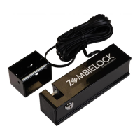
Details on connecting and operating the AXZL Zombie Gate Lock with the system.
Explanation of how hardwired devices use "DRY CONTACT" input signals.
How signals must transition from INACTIVE to ACTIVE for system recognition.
Using the OPEN terminal for vehicle detectors to open the gate.
Using CLS-RVRS terminal with photo eyes or safety edges for closing reversal.
Using OPN-RVRS terminal with photo eyes or safety edges for opening reversal.
Details on terminals for reverse opening and closing, and what happens when beams are blocked.
Instructions for manually opening or closing the gate by releasing the front mount.
Procedure to disconnect the operator power and disengage ZombieLock if installed.
Features of the premium remote, including PartyMode and battery status.
Description of the standard remote for controlling up to two gate systems.
Features of the water-resistant remote, suitable for outdoor use.
Information on the wireless keypad for access and activating features like VacationMode.
A bracket for mounting keypads or transmitters to posts or columns.
Details on 10W and 30W solar panels for remote locations without AC power.
Kit providing two 7 Amp hour 12V batteries to power the gate opener system.
Primary power source battery for gate openers when auto/marine batteries are not used.
Information on the patented ZombieLock for automatic gate locking technology.
Mounting bracket kits for attaching devices to tubular gates.
Sensor for triggering gate opening upon vehicle exit, buried underground.
Wireless sensor for triggering gate opening upon vehicle exit, buried underground.
Standard push button for controlling single or dual gate systems via low voltage wire.
Pin for securing the operator rear mount with a padlock.
Low voltage wire for transformer or solar panel power connections.
Adjustable photo eyes for outdoor environments, available in monitored and non-monitored versions.
Required bracket kit for gates swinging out from the property.
| Gate Type | Swing |
|---|---|
| Solar Compatible | Yes |
| Obstruction Sensing | Yes |
| Auto Close | Yes |
| Control Type | Radio Remote |
| Battery Backup | Yes |
| Remote Control Included | Yes |
| Safety Features | Obstruction sensing |