A8 Test Points
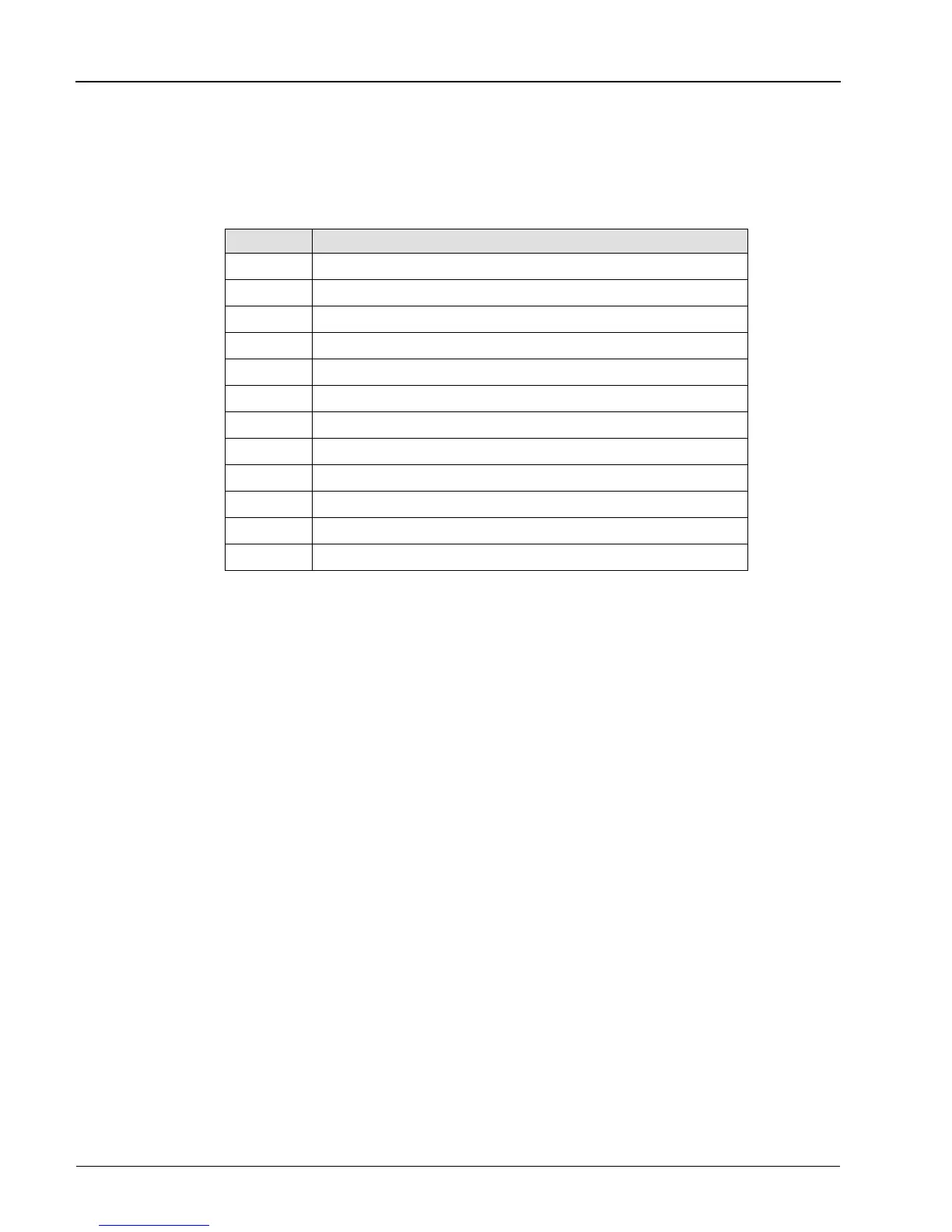
The test points in Table 4-6 can be checked for the correct signals on the A8 Interface Assembly:
Test Point Description
TP1 5 V Common
TP2 Clock - 2 MHz
TP3 +5 V
TP4 Shift Signal
TP5 I Sense
TP6 Timer (100 ms pulse from spin knob movement)
TP7 Flyback
TP8 -HV
TP9 +HV
TP10 +20 V Unregulated
TP11 +MV
TP12 A Ground
Table 4-6. A8 Interface Assembly Test Points
Series 8500A Peak Power Meters
4-26
Manual No. 20790, Rev C, November 1998
 Loading...

