2.4 Front Panel Description
The front panel controls, display, and connections are described in this section. The boxed numbers in
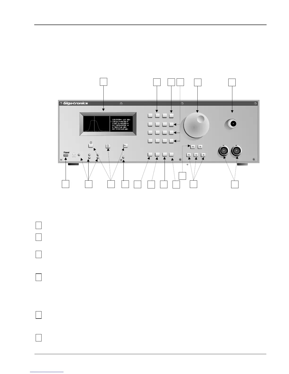
Figure 2-5 correspond to the boxed numbers in the description. The Peak, CW, and Graph keys in both
power meter models, and the Detector Select A and B keys of the Model 8502A contain lights in the
center of the buttons to indicate when the functions are active.
1
Power This is the push-on push-off ac power switch to the PPM.
2
Display This is an Electro Luminescent (EL) alphanumeric and graphic display screen. It
presents data and shows pulse waveform profiles.
3
GPIB
Indicators
These LEDs indicate whether the PPM is under local or remote control and the
current GPIB status (REM = remote control on, LSN = listen, TLK = talk, SRQ =
service request, and LLO = local lockout.)
4
F1, F2, F3
Directional keys
Backspace
The F1 (up) and F2 (down) directional keys are used in the Graph Mode to move the
cursor (∆ icon) up and down to select any pulse or cursor parameters that are to be
changed. The F3 (backspace) key is for correcting entered text or numbers.
A secondary function of these keys is to select menu functions as the various menus
are displayed.
5
Ready, New Data
Indicators
These LEDs flash whenever the system is receiving a trigger. If the Ready light is
steadily on and the New Data light is off, it would indicate that a trigger was not
being received.
6
Data Entry Use this 12-button keypad to enter parameter data when instructed in the applicable
procedure.
Peak PowerMeter
Model 8502A
7
8
9
1
0
.
_
ns
ms
µ
s
Clear
F1
F2
F3
2
3
4
5
6
GHz kW
dB W
dBm mW
On
Off
LL0
GPIB
REM
SRQ
LSN
TLK
Ready
New Data
Pulse/
Cursor Mem
Freq
Menu
Detector Select
A
B
Peak CW
Graph
Autoscale
DetectorInput
A
B
Calibrator
1GHz
Bksp
2
67
8
13
17
10
11
12
15
16
14
3
4
5
9
1
Figure 2-5. Model 8502A Front Panel
Operation
Manual No. 20790, Rev C, November 1998
2-7

 Loading...
