2.8.9 Pulse Parameters Sub-Mode Functions
Commonly used timing measurements required when analyzing pulsed RF/microwave signals are:
• Pulse Width
• Rise time
• Fall time
• Peak Power
• Repetition Rate
The pulse parameter readout allows the first four of these parameters to be measured directly by the PPM
and displayed on the readout window. Auxiliary equipment may sometimes be required to measure
repetition rate.
While in the GRAPH Mode, the Pulse sub-mode routine is entered by pressing
[PULSE/CURSOR/MARKER].
Pulse Rise Time, Width, and Fall Time
The PPM displays the time between three pairs of start and stop power percentages. The default values
for start and stop percentages are:
Measurement Start % Stop %
Rise time 10% rising edge 90% rising edge
Fall time 90% falling edge 10% falling edge
Pulse Width 50% rising edge 50% falling edge
These parameters can be set or changed as follows:
1. Press [PULSE/CURSOR/MARKER] to display the pulse parameters.
2. Move the cursor (using either the up or down arrow key) to the Pulse Width line on the display.
The current Start % setting will be displayed.
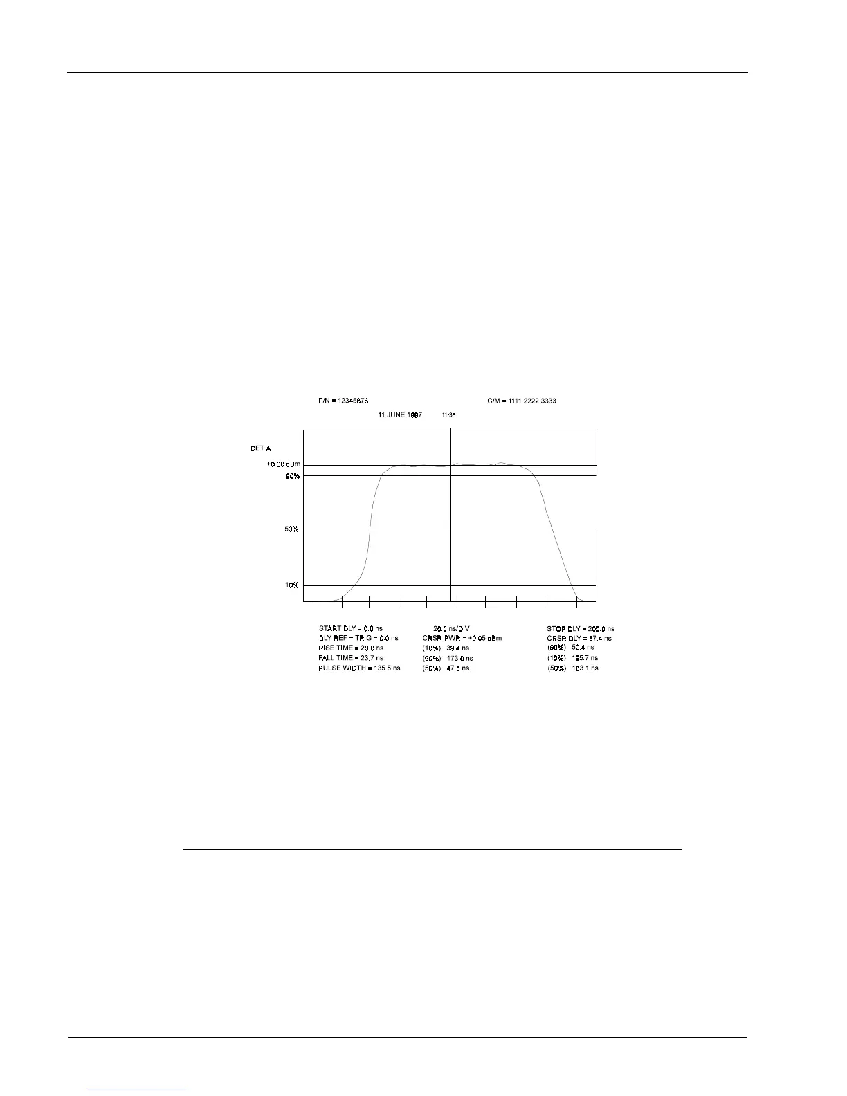
Figure 2-9. Typical Pulse Sub-Mode Digital Plot
Series 8500A Peak Power Meters
2-26
Manual No. 20790, Rev C, November 1998

 Loading...
