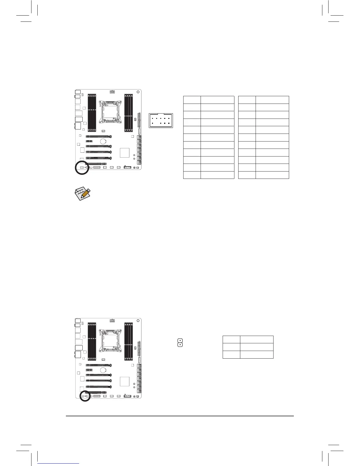
11) F_AUDIO (Front Panel Audio Header)
The front panel audio header supports Intel High Denition audio (HD) and AC'97 audio. You may connect
your chassis front panel audio module to this header. Make sure the wire assignments of the module
connector match the pin assignments of the motherboard header. Incorrect connection between the module
connector and the motherboard header will make the device unable to work or even damage it.
• The front panel audio header supports HD audio by default. If your chassis provides an AC'97
front panel audio module, refer to the instructions on how to activate AC'97 functionality via the
audio software in Chapter 5, "Conguring 2/4/5.1/7.1-Channel Audio."
• Audio signals will be present on both of the front and back panel audio connections simultaneously.
If you want to mute the back panel audio (only supported when using an HD front panel audio
module), refer to Chapter 5, "Conguring 2/4/5.1/7.1-Channel Audio."
• Some chassis provide a front panel audio module that has separated connectors on each wire
instead of a single plug. For information about connecting the front panel audio module that has
different wire assignments, please contact the chassis manufacturer.
1
12) SPDIF_O (S/PDIF Out Header)
This header supports digital S/PDIF Out and connects a S/PDIF digital audio cable (provided by expansion
cards) for digital audio output from your motherboard to certain expansion cards like graphics cards and
sound cards. For example, some graphics cards may require you to use a S/PDIF digital audio cable for
digital audio output from your motherboard to your graphics card if you wish to connect an HDMI display
to the graphics card and have digital audio output from the HDMI display at the same time.
For information about connecting the S/PDIF digital audio cable, carefully read the manual for your
expansion card.
For HD Front Panel Audio:
Pin No. Denition
1 MIC2_L
2 GND
3 MIC2_R
4 -ACZ_DET
5 LINE2_R
6 GND
7 FAUDIO_JD
8 No Pin
9 LINE2_L
10 GND
For AC'97 Front Panel Audio:
Pin No. Denition
1 MIC
2 GND
3 MIC Power
4 NC
5 Line Out (R)
6 NC
7 NC
8 No Pin
9 Line Out (L)
10 NC
 Loading...