F_USB30
F_AUDIO(H)
DB_PORT
F_PANEL(NH) F_PANEL
(H61M-D2)
ACPI_CPT
(GA-IVB)
BIOS_PH
(GA-IVB)
SMB_CPT
(GA-IVB)
CLR_CMOS
CI
DIS_ME
GP15_CPT
(GA-IVB)
XDP_CPU
XDP_PCH
(GA-IVB)
TPM
w/housing
Voltage measurement module(X58A-OC)
PCIe power connector (SATA)(X58A-OC)
DIP
123
DIP
123
DIP
123
DIP
123
1
1
1
1
BIOS Switcher (X58A-OC)
PWM Switch (X58A-OC)
M_SATA
PWM Switch (SW1)(X79-UD7)
DIP
1 2 3 4 5
Voltage measurement points(G1.Sniper 3)
BIOS Switcher (SW4)
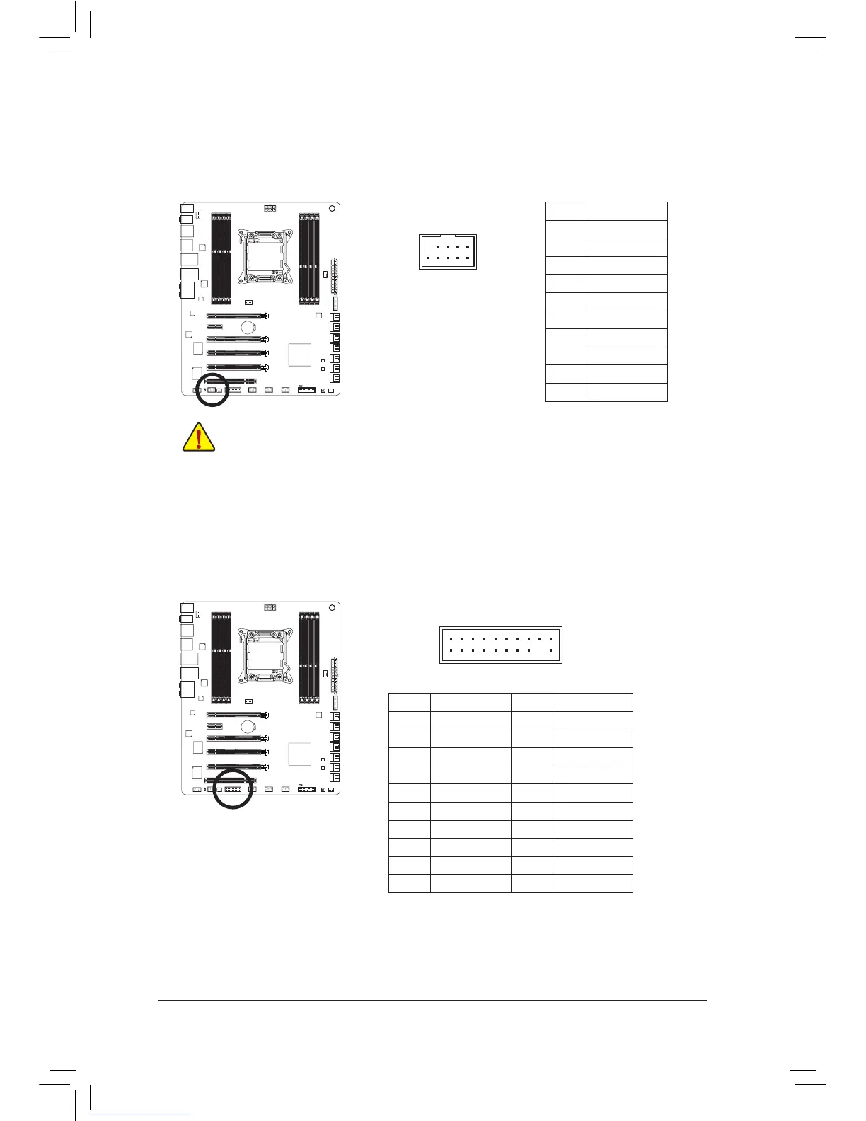
16) TPM (Trusted Platform Module Header)
You may connect a TPM (Trusted Platform Module) to this header.
Pin No. Denition Pin No. Denition
1 LCLK 11 LAD0
2 GND 12 GND
3 LFRAME 13 NC
4 No Pin 14 ID
5 LRESET 15 SB3V
6 NC 16 SERIRQ
7 LAD3 17 GND
8 LAD2 18 NC
9 VCC3 19 NC
10 LAD1 20 SUSCLK
15) F_1394 (IEEE 1394a Header)
The header conforms to IEEE 1394a specication. The IEEE 1394a header can provide one IEEE 1394a
port via an optional IEEE 1394a bracket. For purchasing the optional IEEE 1394a bracket, please contact
the local dealer.
10
9
2
1
• Do not plug the USB bracket cable into the IEEE 1394a header.
• Prior to installing the IEEE 1394a bracket, be sure to turn off your computer and unplug the power
cord from the power outlet to prevent damage to the IEEE 1394a bracket.
• To connect an IEEE 1394a device, attach one end of the device cable to your computer and then
attach the other end of the cable to the IEEE 1394a device. Ensure that the cable is securely
connected.
Pin No. Denition
1 I-TPA1+
2 I-TPA1-
3 GND
4 GND
5 I-TPB1+
6 I-TPB1-
7 Power (12V)
8 Power (12V)
9 No Pin
10 GND
 Loading...