- 6 -
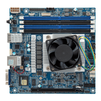
Item Code Description
1 VGA VGA Port
2 80H 80 Debug Port
3 BAT Battery Cable Connector
4 USB3_MLAN Server Management LAN Port (Top)/ USB3.1 Ports (Bottom)
5 IPMB IPMB Connector
6 LAN1_2
GbE Ethernet LAN Port #1 Support NCSI (Top)/
GbE Ethernet LAN Port #2 (Bottom)
7 SW_PWR_ID Power Button (Top)/ ID Button with LED (Bottom)
8 P12V_AUX1 2x4 Pin 12V Power Connector
9 SGPIO1 SATA SGPIO Connector
10 FP_1 Front Panel Header
11 BP_1 HDD Back Plane Board Connector
12 PMBUS PMBus Connector
13 DC_IN1 2x2 Pin 5VSB/PSON Power Connector
14 SATA0 SATA III 6Gb/s Connector #0
15 SATA1 SATA III 6Gb/s Connector #1
16 SATA2 SATA III 6Gb/s Connector #2
17 SATA3 SATA III 6Gb/s Connector #3
18 SL_SAS SlimLine SAS 4i Connector (SATA III/ PCIe Signal)
19 CPU0_FAN CPU Fan Connector
20 SYS_FAN1 System Fan Connector #1
21 SYS_FAN2 System Fan Connector #2
22 F_USB3 Front Panel USB 3.1 Connector
23 COM1 Serial Port Header
24 M2_M M.2 slot (PCIe Gen3 x4, Support NGFF-2280)
25 PCIE_1 PCIe x16 Slot (Gen3 x16)
 Loading...