To replace the components, proceed as follows:
(1) Level indicator:
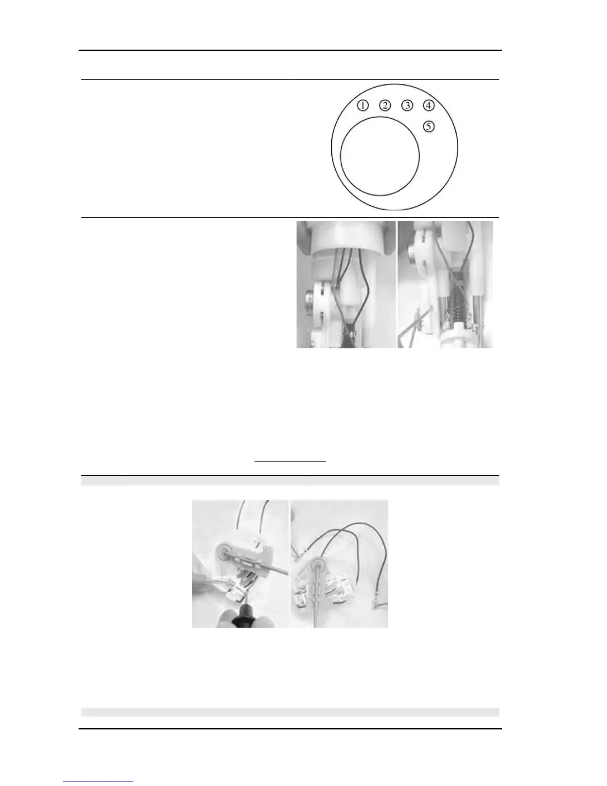
- Note the assembly position and the path of the
two connecting wires.
pos 2 = wire connected to the circuit
pos 3 = wire connected to the movable arm
Pass the wires through the hole found between fil-
ter and pressure regulator.
- Disconnect and extract the wires
- Using a screwdriver on the retain tab as shown
in the figure, extract the level indicator from the
support
- Level indicator check
The check may also be carried out before removing it from the support.
Measure the resistance between the two level indicator wires.
Moving the float arm, check that the resistance is subject to gradual variations according to the arm
motion.
LIMIT VALUES
Specification
Desc./Quantity
1 Empty tank position: 95 - 105 Ω
2 Full tank position: 0 - 9 Ω
- To refit, repeat the removal operations but in reverse order.
(2) Pressure regulator:
- Remove the locking spring
- Extract the pressure regulator with sealing rings.
N.B.
Injection Nexus 500 euro 3
INJEC - 230