Removal
- Remove the front handlebar cover.
- Drain off the braking system corresponding to the
circuit being tested.
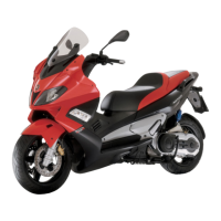
- Remove the two fixing screws from the brake
pump to the handlebar indicated in the photo-
graph.
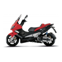
- Remove the oil pipe fitting from the pump undoing
the screw indicated in the figure.
- Remove the stop light switch connector
BRAKE PUMP TECHNICAL DATA
Specification
Desc./Quantity
Pump right piston diameter: Ø 12
Pump left piston diameter: Ø 15
Refitting
To refit, carry out the removal operations but in reverse order, respecting the prescribed locking torques.
Locking torques (N*m)
Pipe / brake calliper coupling 20 ÷ 25
Rear brake pump - combined
Braking system Nexus 500 euro 3
BRAK SYS - 324