4. Installation4. Installation
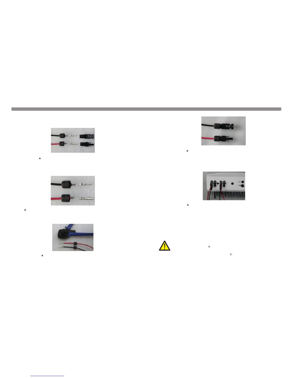
iii) Crimp the contact pin to the wire using a proper wire crimper as shown in Figure 4.9
Figure 4.9 Crimp the contact pin to the wire
iv) Insert the contact pin to the top part of the connector and screw up the cap nut to
the top part of the connector (as shown in Figure 4.10).
The steps to assemble the DC connectors are listed as follows:
I) Strip off the DC wire for about 7mm, Disassemble the connector cap nut (see Figure 4.7).
ii) Insert the wire into the connector cap nut and contact pin as shown in Figure 4.8.
Figure 4.7 Disassemble the Connector Cap nut
Figure 4.8 Insert the Wire into the Connector Cap nut and contact pin
Figure 4.10 Connector with Cap nut Screwed on
Figure 4.11 Connect the DC Connectors to the Inverter
v) Then connect the DC connectors to the inverter. Small click will confirm connection
(as shown in Figure 4.11).
4. Assemble the grid side connector of the Inverter.
For all AC connections, 2.5- 6mm 105 ℃ cable is required to be used. Please make sure
2
the resistance of cable is lower than 1.5 ohm. If the wire is longer than 20m, it's
recommended to use 6mm cable.
2
WARNING:
There are symbols marked inside the connector ( see
Figure4.12), the Line wire of grid must be connected to terminal; the “L” “1” “2”
Earth wire of grid must be connected to“ ”;it is recommended that the
Neutral wire of grid is connected to“N”terminal (not required)
“L” “1” “2” “N” “ ”
.14. .15.