Radio Control Wiring
In order to operate the door with a wireless remote, an independent Radio Control Unit may be installed and
connected to the Glidermatic control unit.
Always disconnect power to unit BEFORE making any setting changes.
CAUTION:
Glidermatic™
Commercial Door Operator
User Manual
11
Ground
+V
Single
STOP
DOWN
UP
It is essential that a supplementary safety device such as a Sensing Edge or Photo Electric Cell be
fi tted when radio control unit is installed to prevent injury or entrapment
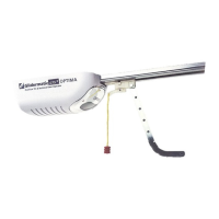
Power to the receiver is supplied from terminals 5
& 6 of J3
5 is +v, 6 is ground
Ensure Jumper JP2 is confi gured to match
required voltage of radio control receiver. (5,
12 or 24VDC)
Single (Up/Down) Output Type Receiver
Connect output of receiver to terminal 4 of J3
Open/Close/Stop Type Receiver
Connect terminals Up, Down and
Stop of Radio Control Receiver to
1, 2 & 3 respectively
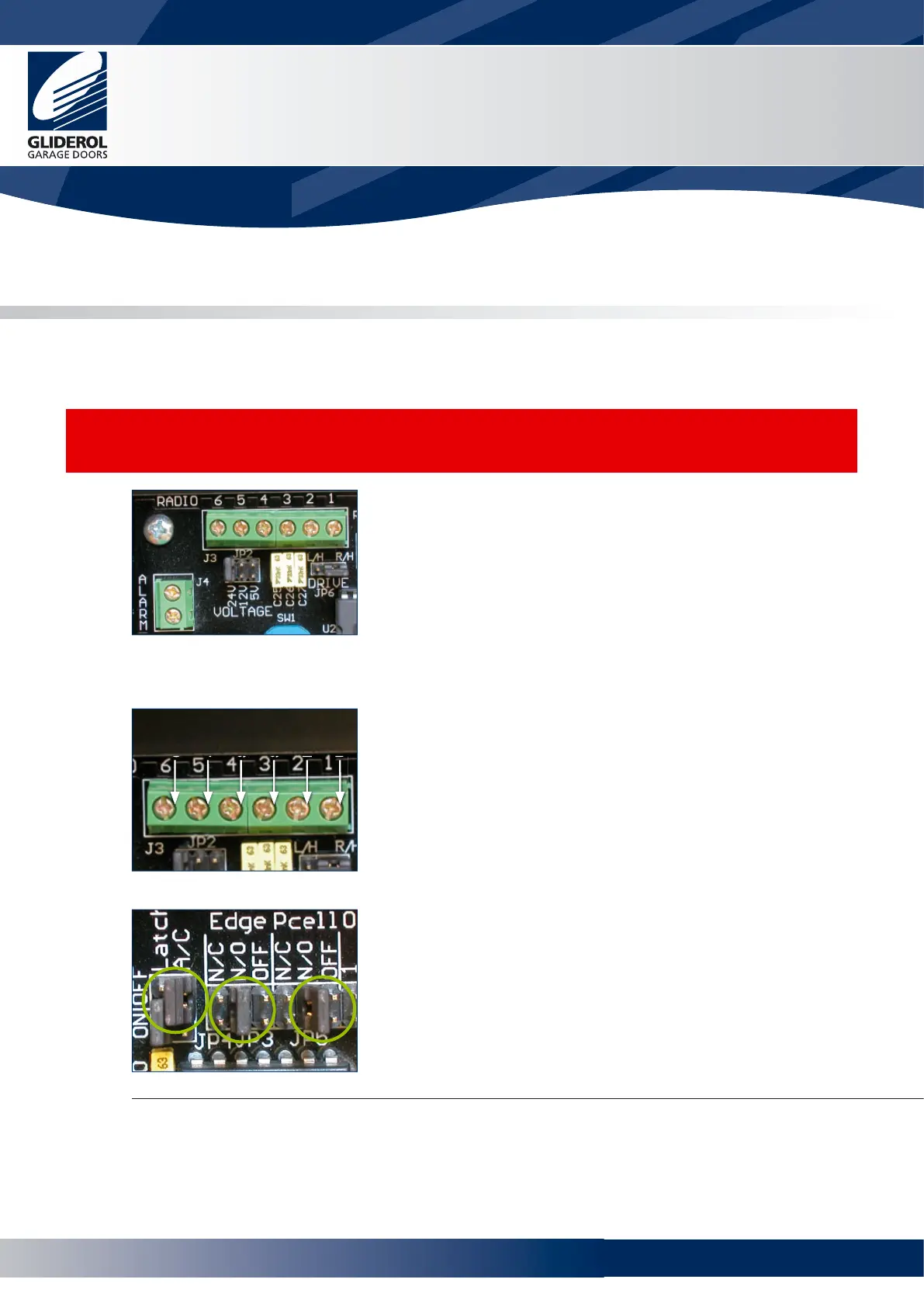
Ensure the jumper JP4 Latch terminal is set to ON
Edge jumper JP3 is set to N/O or N/C
Pcell jumper JP3 is set to N/O or N/C
In accordance with the instructions supplied by the
manufacturer of the supplementary safety system
Once any radio receiver unit is connected the unit will not operate unless a supplementary safety device is
fi tted and the jumpers at JP3 and JP5 set accordingly. Refer to pages 9 and 10.
www.garagedoorsonline.co.uk
 Loading...