7 Start-up
20 Installation and maintenance instructions EASICOM 3 0020239562_02
▶ You must not start up the boiler.
Conditions: Gas flow pressure in the permissible range
▶ End the check programme P.01.
▶ Allow the boiler to cool down allowing pump overrun to
operate for a minimum of two minutes.
▶ Close the gas isolator cock (1).
▶ Remove the pressure gauge and retighten the sealing
screw (2) for the measuring nipple.
▶ Open the gas isolator cock (1).
▶ Check the measuring nipple for gas tightness.
▶ Install the front casing. (→ Page 10)
▶ Reset boiler controls for normal operation.
▶ Record the appliance gas inlet working pressure (kPa
resp. mbar) in the Benchmark gas boiler commissioning
checklist.
7.9.3 Checking the leak-tightness of the flue gas
installation and flue gas recirculation
1. Check the flue gas installation is intact in accordance
with the latest gas safe technical bulletin and informa-
tion supplied in the installation instructions.
2. For extended flue gas installations check for flue gas
recirculation using the air analysis point.
3. Use a flue gas analyser.
4. If you discover CO or CO
2
in the supply air, search for
the leak in the flue gas installation or for signs of flue
gas recirculation.
5. Eliminate the damage properly.
6. Check again whether the supply air contains any CO or
CO
2
.
7. If you cannot eliminate the damage, do not start up the
product.
7.9.4 Thoroughly flushing the heating installation
("hot")
1. Operate the appliance until the boiler and the heating
system are up to temperature.
2. Check the heating system for leaks.
3. Connect a hose to the drain valve located at the lowest
position of the heating system.
4. Shut off the boiler, open the drain valve and all purge
valves on the radiators and allow the water to flow out
of the heating system and the boiler quickly and fully.
5. Close the drain valve.
6. Fill and purge the heating installation. (→ Page 18)
7. Re-fill the system until the system design pressure of
0,1 MPa (1,0 bar) is attained.
Note
The actual reading on the digital pressure
gauge should ideally be 0,05 MPa (0,5 bar)
plus an additional pressure corresponding
to the highest point of the system above the
base of the boiler – 10 m head equals an ad-
ditional 1 bar reading on the pressure gauge.
The minimum pressure should not be less
than 0,1 MPa (1 bar) in any installation. If
the system is to be treated with an inhibitor it
should be applied at this stage in accordance
with the manufacturer’s instructions. Further
information can be obtained from Sentinel,
Betz Dearborn Ltd., Tel: 0151 420 9595, or
Fernox, Alpha– Fry technologies. Tel: 0870
8700362.
8. Install the front casing. (→ Page 10)
7.9.5 Checking the CO₂ content
1. Start up the product with the check programme (P.01)
and set the value.
– Setting value for the programme P.01: 100
Check programmes – Overview (→ Page 30)
2. Wait until the value that is read is stable.
– Waiting period for reading a stable value: 5 min
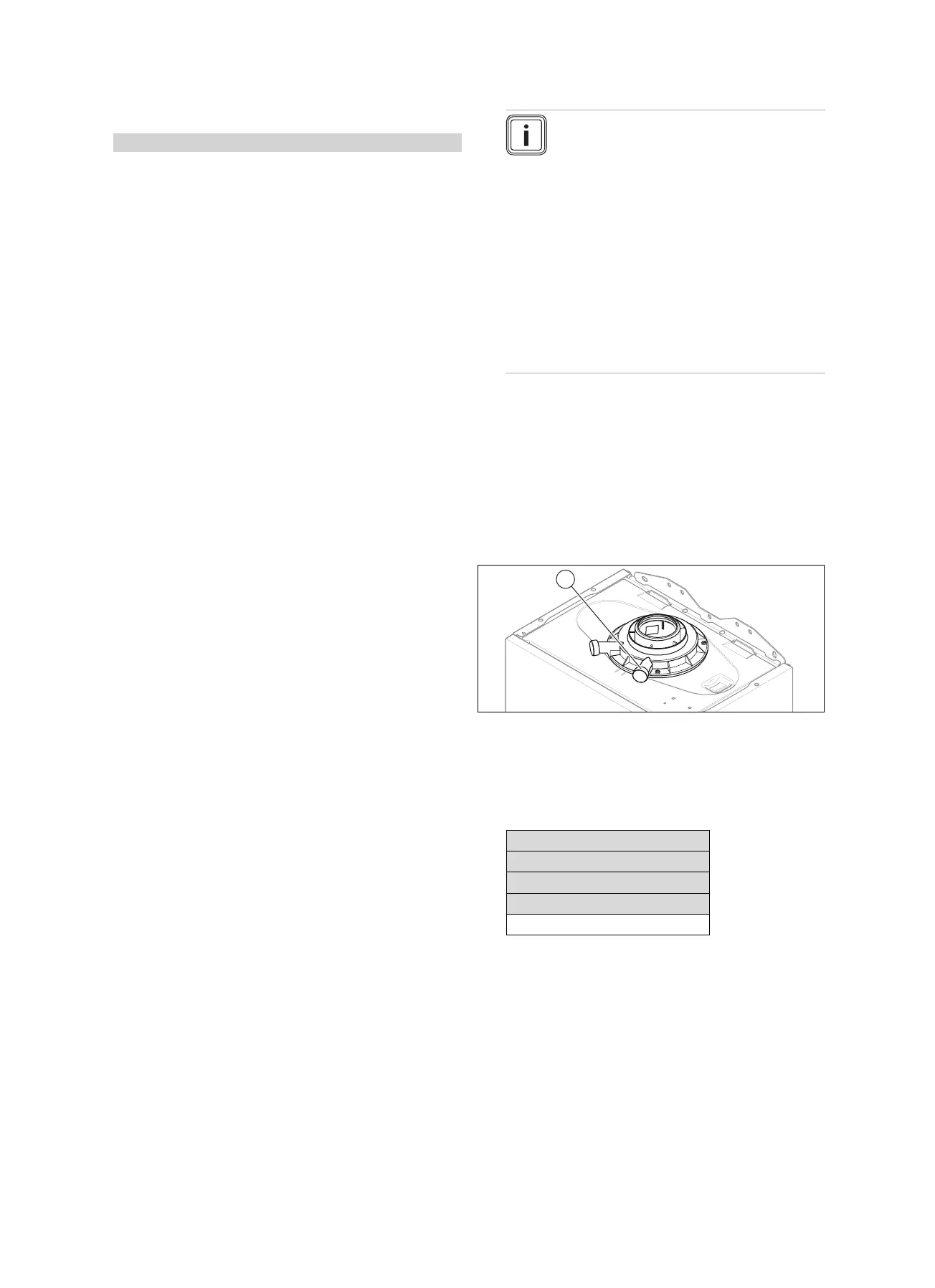
3. Unscrew the cover from the flue gas analysis point (1).
4. Measure the CO₂ content at the flue gas analysis point
(1).
5. Compare the measured value with the corresponding
value in the table.
Checking the CO₂ content
Great Britain
front casing on / front casing off
Natural gas
G20
9.2 ±1 %
◁ The value is OK.
▽ The value is not OK; you cannot start up the
product.
▶ Inform Customer Service.
 Loading...


