Adapting the unit to the heating installation 8
0020239562_02 EASICOM 3 Installation and maintenance instructions 21
7.10 Checking leak-tightness
▶ Check the gas pipe, the heating circuit and the hot water
circuit for leak-tightness.
▶ Check that the air/flue pipe has been installed correctly.
Conditions: Room-sealed operation
▶ Check whether the vacuum chamber has been closed
tightly.
7.10.1 Checking the heating mode
1. Activate the heating mode on the user interface.
2. Turn all thermostatic radiator valves on the radiators
until they are fully open.
3. Allow the product to operate for at least 15 minutes.
4. Purge the heating installation.
5. Activate the display for the current operating status.
(→ Page 16)
Status codes – Overview (→ Page 34)
◁ If the product is working correctly, the display shows
S.04.
7.10.2 Checking the hot water generation
1. Activate the hot water handling mode on the user
interface.
2. Open a hot water valve completely.
3. Activate the display for the current operating status.
(→ Page 16)
Status codes – Overview (→ Page 34)
◁ If the product is working correctly, the display shows
S.14.
8 Adapting the unit to the heating
installation
You can reset/change the system parameters (section "Us-
ing diagnostics codes").
Overview of diagnostics codes (→ Page 30)
8.1 Burner anti-cycling time
To prevent frequent switching on and off of the burner and
thus prevent energy losses, an electronic restart lockout
is activated for a specific period each time the burner is
switched off. The burner anti-cycling time is only active for
the heating mode. Hot water handling mode during a burner
anti-cycling time does not affect the time function element.
8.1.1 Setting the maximum burner anti-cycling
time
1. Set the diagnostics code. (→ Page 15)
Overview of diagnostics codes (→ Page 30)
2. If required, adjust the maximum burner anti-cycling time
using the diagnostics code d.02.
8.1.2 Resetting the remaining burner anti-cycling
time
▶
Hold the button down for more than 3 seconds.
◁
is shown in the display.
8.2 Setting the pump output
Conditions: Two-stage pump
▶ If required, use diagnostics code d.19 to adjust the set-
ting for the operating-mode-dependent pump speed.
▶ Set the diagnostics code. (→ Page 15)
Overview of diagnostics codes (→ Page 30)
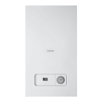
Flow rate-pressure curves for 24 kW
(pressure measured downstream of the valves)
21
3 4
60
70
50
30
20
40
10
0 500 1000 1500 A
B
1 Maximum speed (by-
pass closed)
2 Maximum speed (de-
fault setting for the by-
pass)
3 Minimum speed (default
setting for the bypass)
4 Flow rate at maximum
output (ΔT = 20K)
A Throughput in circuit
(l/h)
B Available pressure
(kPa)
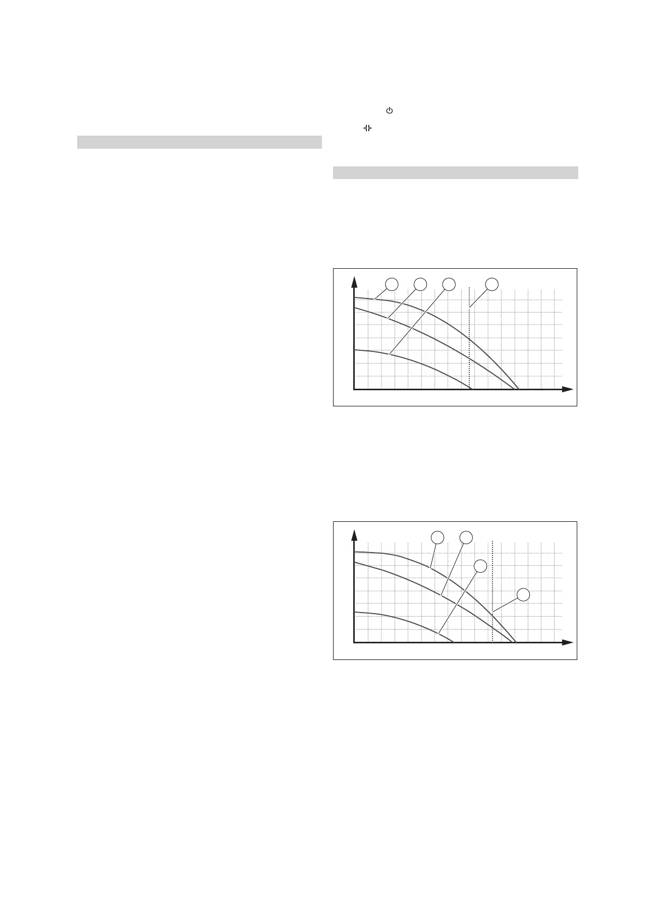
Flow rate-pressure curves for 28 kW
(pressure measured downstream of the valves)
21
3
4
60
70
50
30
20
40
10
0 500 1000 1500 A
B
1 Maximum speed (by-
pass closed)
2 Maximum speed (de-
fault setting for the by-
pass)
3 Minimum speed (default
setting for the bypass)
4 Flow rate at maximum
output (ΔT = 20K)
A Throughput in circuit
(l/h)
B Available pressure
(kPa)
 Loading...


