4 Set-up
10 Installation and maintenance instructions Energy 2 0020283671_03
2. Check if the supplied fixing material may be used for
the wall.
Condition: The load-bearing capacity of the wall is sufficient, The fixing ma-
terial is permitted for the wall
▶ Wall-mount the product as described.
Condition: The load-bearing capacity of the wall is not sufficient
▶ Ensure that wall-mounting apparatus on-site has a suf-
ficient load-bearing capacity. Use individual stands or
primary walling, for example.
▶ Do not wall-mount the product if you cannot provide
wall-mounting apparatus with a sufficient load-bearing
capacity.
Condition: The fixing material is not permitted for the wall
▶ Wall-mount the product as described using the permitted
fixing material provided on-site.
Condition: Installation in a mobile home
▶ If you want to permanently install the product in a mo-
bile home ("stationary installation"), additional fasten-
ings that are specified by the manufacturer of the mobile
home may also be required. The additional fastenings
are used to correctly secure the product while driving.
Before using the product, it must be checked by a qual-
ified person in order to ensure that it is permanently se-
curely fastened and is safe to use.
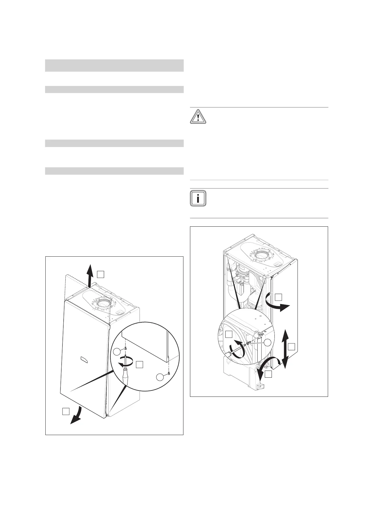
4.8 Removing/installing the front casing
4.8.1 Removing the front casing
1. Undo the two screws (1).
2. Gently press the front casing backwards in the centre
so that the latching lug is released.
3. Pull the front casing forwards at the bottom edge.
4. Lift the front casing upwards from the bracket.
4.8.2 Installing the front casing
▶ Refit the components in the reverse order.
4.9 Removing/installing the side section
4.9.1 Removing the side section
Caution.
Risk of material damage caused by mech-
anical deformation.
Removing both side sections may cause
mechanical distortion in the product, which
may cause damage to the piping, for ex-
ample, and potentially result in leaks.
▶ Always only remove one side section –
never both side sections at the same time.
Note
If there is sufficient lateral clearance (at least
70 mm), you can remove the side section to fa-
cilitate maintenance or repair work.
1. Hinge the electronics box forward.
2. Hold on to the side section so that it cannot fall and
unscrew both screws (1), one from the top and one
from the bottom.
3. Tilt the side section to the outside and move it down-
wards and out.

 Loading...
