Adapting the unit to the installation 8
0020283671_03 Energy 2 Installation and maintenance instructions 21
Status codes – Overview (→ Page 33)
◁ If the product is working correctly, the display shows
S.14.
8 Adapting the unit to the installation
You can reset/change the system parameters (section "Us-
ing diagnostics codes").
Overview of diagnostics codes (→ Page 29)
8.1 Setting the burner anti-cycling time
To prevent frequent switching on and off of the burner and
thus prevent energy losses, an electronic restart lockout
is activated for a specific period each time the burner is
switched off. The burner anti-cycling time is only active for
the heating mode. Domestic hot water mode during a burner
anti-cycling time does not affect the time function element.
8.1.1 Setting the maximum burner anti-cycling
time
1. Set diagnostics code . (→ Page 15)
Overview of diagnostics codes (→ Page 29)
2. If required, adjust the maximum burner anti-cycling time
using the diagnostics code d.02.
8.1.2 Resetting the remaining burner anti-cycling
time
▶ Hold the button down for more than 3 seconds.
◁ is shown in the display.
8.2 Setting the pump output
The product is equipped with a speed-regulated high-effi-
ciency pump, which adjusts independently to the hydraulic
conditions of the heating installation.
If you have installed a low loss header in the heating install-
ation, you should switch off the speed regulation and set the
pump output to a fixed value.
▶ If required, change the setting of the pump speed, which
depends on the operating mode, under diagnostics code
d.14.
▶ Set diagnostics code . (→ Page 15)
Overview of diagnostics codes (→ Page 29)
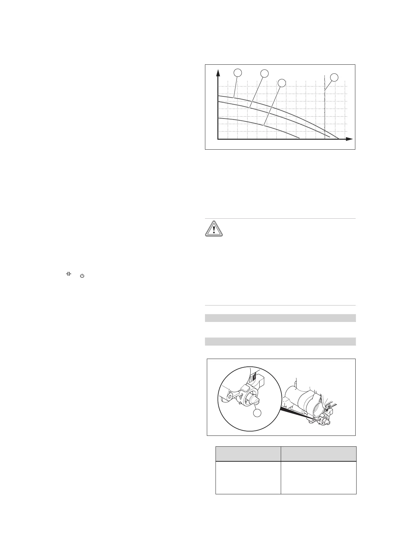
Flow rate-pressure curves for 30 kW
(pressure measured downstream of the valves)
A
B
0
10
20
30
40
50
60
0 200 400 600 800 1000 1200
70
1
2
3
4
1 Maximum speed (by-
pass closed)
2 Maximum speed (de-
fault setting for the by-
pass)
3 Minimum speed (factory
setting for the bypass)
4 Flow rate at maximum
output (ΔT = 20K)
A Throughput in circuit
(l/h)
B Available pressure
(kPa)
8.3 Setting the bypass valve
Caution.
Risk of material damage caused by incor-
rect setting of the high-efficiency pump
If the pressure at the bypass valve is in-
creased (by turning it clockwise) and the
pump output is set to less than 100%, the
product may not operate correctly.
▶ In this case, set the pump output to
5 = 100% using diagnostics parameter
d.14.
Condition: d.14 is set to 0 = auto
▶ Do not change the factory settings.
Condition: d.14 is set to 1 - 5
▶ Remove the front casing. (→ Page 10)
▶ Regulate the pressure using the adjusting screw (1).
Position of the adjusting
screw
Notes/application
Right-hand stop (screwed
all the way in)
If the radiators do not heat
up sufficiently at the default
setting. In this case, you must
set the pump to the maximum
speed.

 Loading...
