12 Decommissioning the product
28 Installation and maintenance instructions Energy 2 0020283671_03
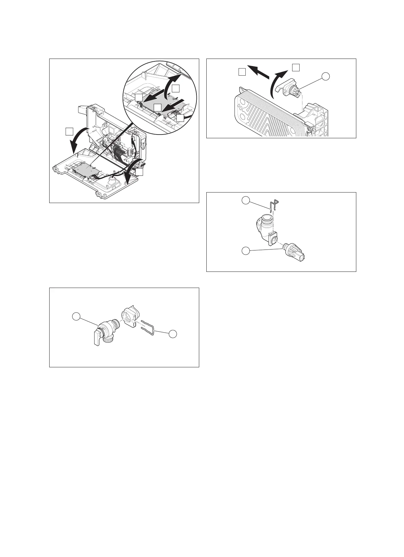
11.6.7 Replacing the PCB for the user interface
1. Open the electronics box.
2. Pull the plug out of the PCB.
3. Undo the clips on the PCB.
4. Remove the PCB.
5. Install the new PCB in such a way that it clicks into the
groove at the bottom and into the clip at the top.
6. Plug in the PCB plug.
7. Close the electronics box.
11.6.8 Replacing the expansion relief valve
1. Remove the clip (2).
2. Remove the expansion relief valve.
3. Fit the new expansion relief valve with a new O-ring.
4. Reattach the clip (2).
11.6.9 Replacing the volume flow sensor
1. Pull out the plug.
2. Remove the volume flow sensor (1).
3. Install the new volume flow sensor.
4. Plug in the plug.
11.6.10 Replace the pressure sensor
1. Pull out the plug.
2. Remove the clip (1).
3. Remove the pressure sensor (2).
4. Install the new pressure sensor.
5. Reattach the clip (1).
12 Decommissioning the product
▶ Switch off the product.
▶ Disconnect the product from the power grid.
▶ Close the gas stopcock.
▶ Close the cold water stop cock.
13 Customer service
For contact details for our customer service department, you
can write to the address that is provided on the back page,
or you can visit www.glow-worm.co.uk.
▶ Check the gas connection pressure (gas flow
pressure).(→ Page 26)
▶ Check the CO₂ content. (→ Page 26)
▶ If required, reset the maintenance interval.(→ Page 37)
▶ Check that the product is leak-tight. (→ Page 20)
▶ Install the front casing.
▶ Fill out the relevant Service Record section in the
Benchmark Checklist in the appendix of this document.
11.7 Completing inspection and maintenance
work

 Loading...
