Supplied By www.heating spares.co Tel. 0161 620 6677
0020085231_02 - 05/10 - Glow-worm
- 9 -
INSTALLATION
i
All the drawings dimensions are shown in mm.
6 Appliance location
6.1 Location
6.1.1 Instructions
Before choosing a site for the appliance, carefully read the
safety warnings and installation manual.
• Ensure that wall to which the appliance will be mounted on is
structurally safe in order to support the weight of the appliance.
• Ensure that the space that the appliance is to be installed
within allows the appliance to be installed and the clearances
maintained. This will ensure that the connections to the
water, gas and ue can be accessed and inspected (see
chapter Clearances).
• Explain these requirements to the appliance user.
• Do not install the appliance above another appliance that
could damage it (for example, above a cooker that might
emit steam or grease) or in a room, which has a lot of dust in
the atmosphere which is corrosive.
• The boiler must be tted inside the property and exposed
pipe work may need to be protected from frost by tting a
frost thermostat.
6.1.2 Regulations
Location
This boiler is not suitable for outdoor installation.
This boiler may be installed in any room, although particular
attention is drawn to the installation of a boiler in a room
containing a bath or shower where reference must be made to
the relevant requirements.
This boiler is suitable for installation in bathroom zones 2 and 3.
In GB this is the current I.E.E. WIRING REGULATIONS and
BUILDING REGULATIONS.
In IE reference should be made to the current edition of I.S.813
“Domestic Gas Installations” and the current ETCI rules.
Timber Frame Buildings
If the boiler is to be installed in a timber frame building it should
be tted in accordance with the Institute of Gas Engineers
document IGE/UP/7/1998. If in doubt seek advice from local
gas undertaking or Glow-worm.
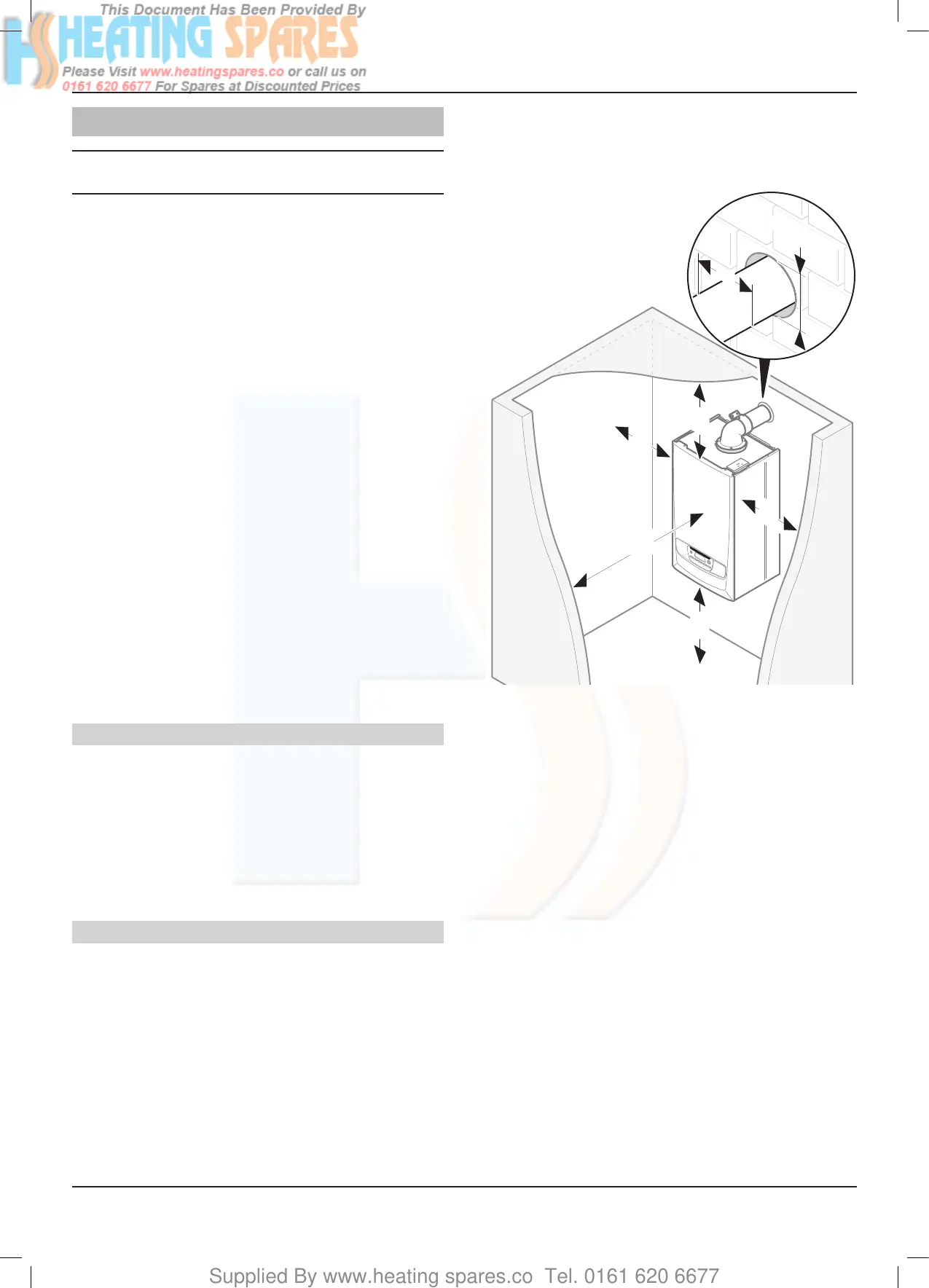
6.2 Clearances
• To allow periodic maintenance, ensure the distances
indicated on the diagram.
Additional clearances may be benecial around the boiler for
installation and servicing.
For ue installations where external access is not practicable,
consideration should be given for the space required to insert
the ue from inside the property, which may necessitate
clearance larger than those specied in diagram below.
ØA
ØA + 5 min.
600*
min.
0
min.
0
min.
200
min.
150
min.
Key
* A removable compartment door can be placed a minimum 5
mm in front of appliance. A clearance of 600 mm is required
fromaxedsurface.
The boiler and ue are suitable for installation onto and through
combustible materials provided that:
- Minimum 5mm clearance is maintained around the
circumference of the ue (air intake).
- The combustible surface and xings are suitable for
supporting the load.
- The minimum clearances from the boiler case are
maintained.
6.3 Ventilation
6.3.1 Room Ventilation
The boiler is room sealed so a permanent air vent is not required.
6.3.2 Cupboard or Compartment Ventilation
Due to the high efciency and low casing temperature of this
boiler, cupboard or compartment ventilation is not necessary.
• Existing ventilation should be investigated for its purpose
before removing.
INSTALLATION
 Loading...


