Supplied By www.heating spares.co Tel. 0161 620 6677
0020085231_02 - 05/10 - Glow-worm
- 53 -
19.7 PCB
i
When replacing the board refer to instructions
supplied with the spare part.
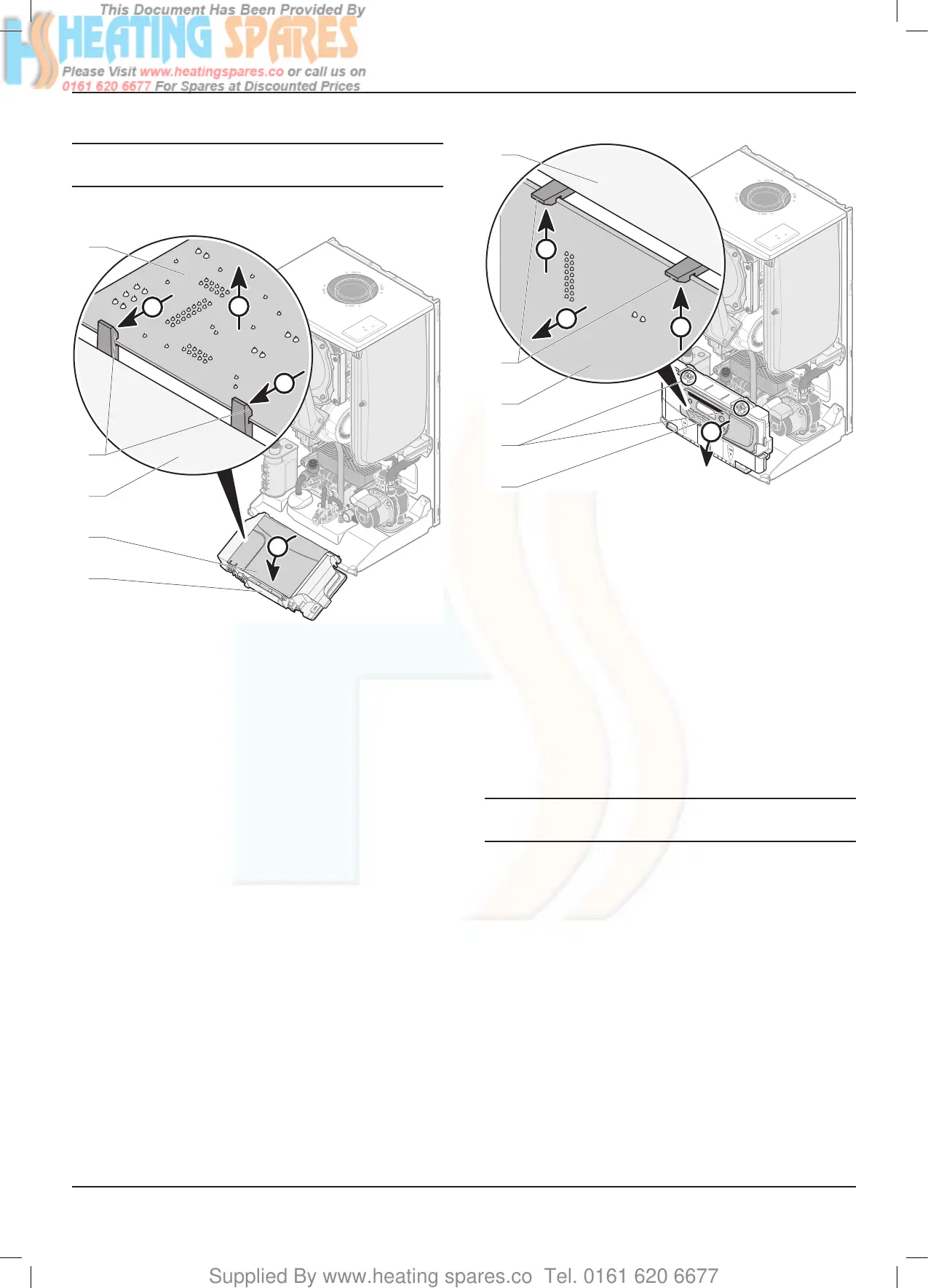
19.8.1 Main PCB
A
B
B
C
4
3
1
2
1
Key
1 Control panel
2 Rear panel
3 Retainings clips
4 Main PCB
• Remove the 24V and 230V connections.
• Remove the rear panel (2).
• Ease back the two PCB retaining clips (3) and withdraw the
PCB from the retaining lugs.
• Remove the electrical connections to the PCB (appliance
interface cable).
• When retting the rear panel, ensure the leads are not
trapped.
19.8.2 2A Fuse Rating
• For access, refer to chapter "Main PCB".
• The fuse is located at top right hand side of the PCB, see
chapter "Electrical connection ►Wiring diagram".
19.8.3 User interface PCB
A
C
B
B
5
4
3
2
1
Key
1 User interface
2 Retaining slots
3 User interface PCB
4 Retainings clips
5 Control Panel
• Remove the user interface (1) easing back the two retaining
slots (2).
• Ease back the two PCB retaining clips (4) and withdraw the
PCB from the retaining lugs.
• Remove the electrical connections to the PCB.
• When retting the user interface, ensure the leads are not
trapped.
19.8.4 Mains supply cable
e
The main supply cable must be replaced by a
qualied and competent electrician.
• If the main supply cable is damaged, replace it refering to the
chapter "Electrical connection".
MAINTENANCE
 Loading...


