Supplied By www.heating spares.co Tel. 0161 620 6677
0020085231_02 - 05/10 - Glow-worm
- 24 -
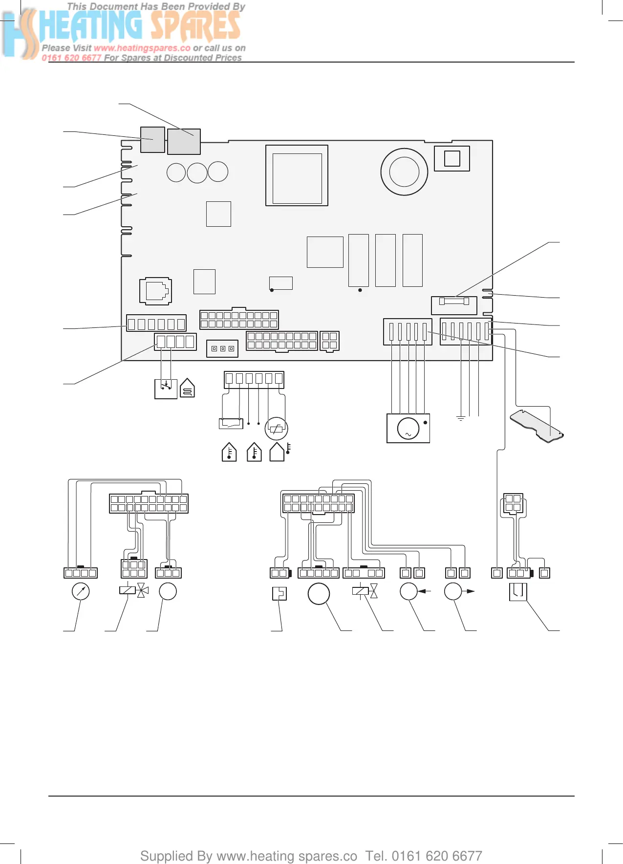
11.6 Wiring diagram
1
10
2
11
3
12
4
13
5
14
6
15
7
16
8
17
9
18
1 2
3 4
10 9 8 7 6 5 4 3 2 1
1920 18 17 16 15 14 13 12 11
M
Green/Yellow
D
M
TT
NTC
Ebus
24 V
X2
X30
X90
X32
X40
X51
X31
X21
230 VAC
LN
X1
X101
FUS
X14
X20
X18
X16
X17
X17
Green/Yellow
Blue
Brown
1 2 3
1
4
2
5
3
6
10 9 8 7 6 5 4 3 2 1
1920 18 17 16 15 14 13 12 11
34 2 1
X2
1 2 345 2 1 1 11 1...89 2 1
1
10
2
11
3
12
4
13
5
14
6
15
7
16
8
17
9
18
X20
1 2
3 4
1
1 2
1
X21
T°C
X18
Green/Yellow
Green/Yellow
19 18 17 16
2
1
3
4
5
6
10
7
9
8
1112131415
Key
1 Overheatingsafetyconnectorforheatingoor
2 Control accessories connector
3 Reserved for future use
4 Location for 24V option card
5 Location for external programmer
6 User interface
7 Fuse 2A
8 Connector for 230 V option
9 Main supply 230V
10 Pump
11 Combinedsparkandamerecognitionelectrode
12 Heating outlet temperature sensor
13 Heating return temperature sensor
14 Gas valve
15 Fan
16 Thermal fuse
17 Waterowsensor
18 Threewayvalve
19 Water pressure sensor
INSTALLATION
 Loading...


