Supplied By www.heating spares.co Tel. 0161 620 6677
0020085231_02 - 05/10 - Glow-worm
- 52 -
19.5.6 Re-assembling the burner group
• Place the burner assembly on the heat exchanger (21).
• Progressively tighten the 4 nuts (12) in an alternate order.
• Reassemble the silencer.
• Connect the gas pipe (36) with a new gasket to the burner
group.
• Connect the spark electrode connector (5) to the igniter unit.
• Connect the connector to the gas valve (37) and the fan (34).
• Open the appliance’s gas input.
• Check the tightness of the gas connection.
19.5.7 HeatingFlowThermistor
• Remove the electrical connections from the thermistor (28).
• Remove the retaining clip from the ow pipe (27).
i
When reconnecting, the polarity of the wiring to
thermistors is not important.
19.5.8 Heating Return Thermistor
• Remove the electrical connections from the thermistor (26).
• Remove the retaining clip from the return pipe (24).
i
When reconnecting, the polarity of the wiring to
thermistors is not important.
19.5.9 Gas valve
• Remove the burner door (11) refering to chapter "Dismantling
the burner door".
• Remove the two gas valve retaining screws (30).
• Remove the gas valve (31) and the gasket (32).
• Fit the new gas valve and the new gasket by repeating the
operations in reverse.
• After assembly test for gas tightness and purge in
accordance with the current issue of BS6891or in IE, the
current edition of I.S.813 “Domestic Gas Installations”.
• Check the combustion CO2.
19.5.10 Fan
• Remove the burner door (11) refering to chapter "Dismantling
the burner door".
• Remove the gas valve (31) (see previous paragraph).
• Loosen the 3 screws (38) located on the burner door (11).
• Remove the fan (33) and the gasket (35).
• Fit the new gasket (35).
• Screw the new fan to the burner door (11).
• After assembly test for gas tightness and purge in
accordance with the current issue of BS6891or in IE, the
current edition of I.S.813 “Domestic Gas Installations”.
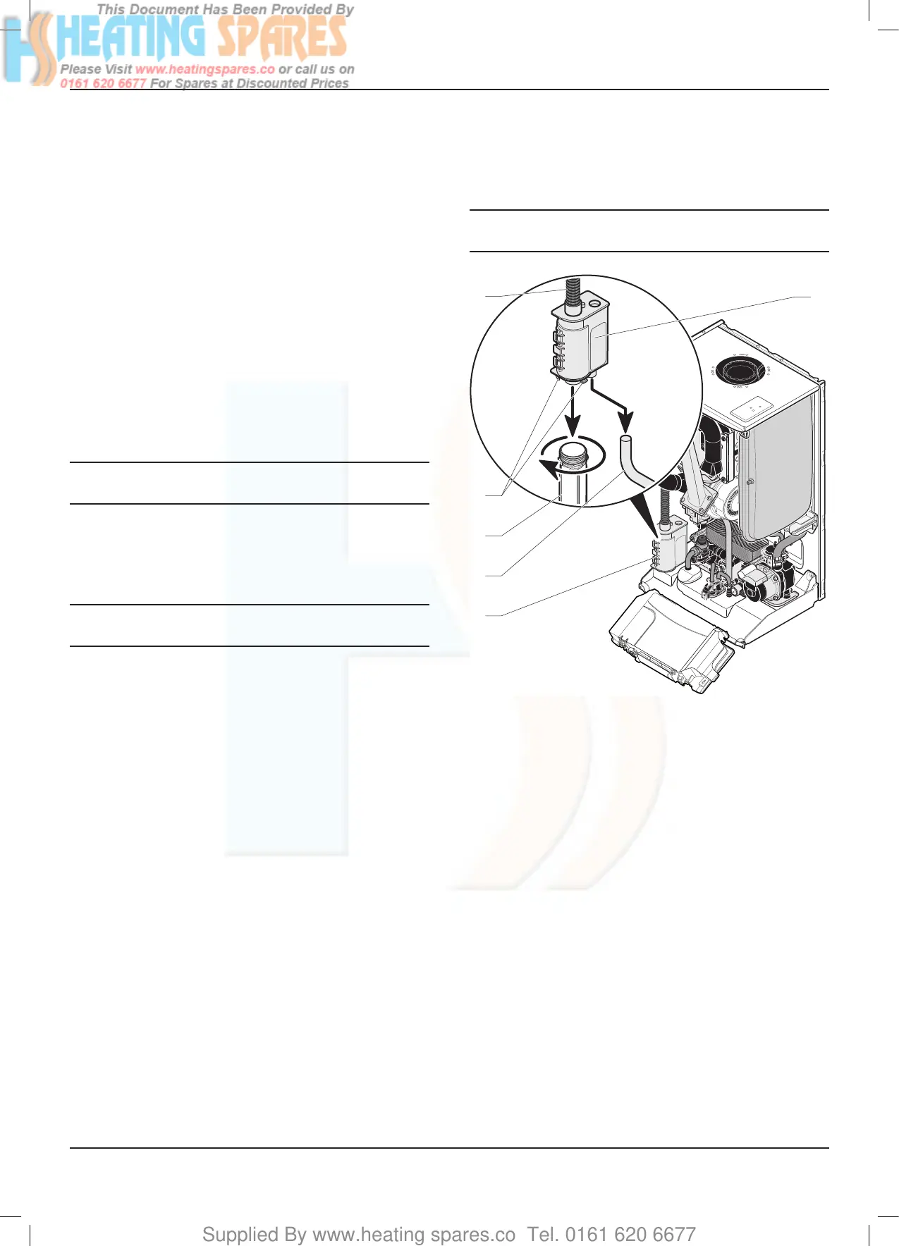
19.6 Condensate trap
a
Warning: condensate is mildly acidic. Wear
protective gloves.
5
4
3
2
1
1
Key
1 Condensate trap
2 Condensate outlet pipe
3 Condensate reservoir
4 Condensate reservoir retaining clips
5 Hose
• Place a container under the condensate trap (1).
• Remove the condensate (3) from the reservoir.
• Disconnect the condensation discharge (2).
• Disconnect the heat exchanger hose (5).
The condense trap will contain water, lift taking care not to spill
the water.
• Remove the condensate trap (1) using the clips (4).
• IMPORTANT: Partially ll the condensate trap with water
before replacing. Start the siphon (3) and ll with water.
MAINTENANCE
 Loading...


