Supplied By www.heating spares.co Tel. 0161 620 6677
0020085231_02 - 05/10 - Glow-worm
- 33 -
MAINTENANCE
To ensure the continued efcient and safe operation of the
boiler it is recommended that it is checked and serviced at
regular intervals. The frequency of servicing will depend upon
the particular installation and usage, but in general once a year
should be enough.
It is the Law that any servicing is carried out by a competent
person approved at the time by the Health and Safety
Executive.
• Before commencing with a service or replacement of parts
isolate the boiler from the electrical supply and turn off the
gas supply at the gas isolation valve.
• When replacing a part on this appliance, use only spare
parts that you can be assured conform to the safety and
performance specication that we require. Do not use
reconditioned or copy parts that have not been clearly
authorised by Glow-worm.
• If any electrical connections have been disconnected
and after their connection, checks to the earth continuity,
polarity, short circuit and resistance to earth must be
repeated using a suitable multimeter, as described in chapter
"Trouble-shooting ► Fault diagnosis ► Check the electrical
installation".
• After servicing, complete the relevant Service Interval
Record section of the Benchmark Checklist located in the
centre pages of this document.
15 Trouble-shooting
15.1 Fault diagnosis
The following checks should be performed before proceeding
onto specic diagnostics:
• Make sure that the electricity supply has not been interrupted
and that the appliance is connected correctly (See chapter
"Trouble-shooting ► Fault diagnosis ► Check the electrical
installation")
• Check the appliance’s gas supply (See chapter "Trouble-
shooting ► Fault diagnosis ► Check the gas supply").
• Ensure that the isolating valves are open.
• Ensure that the pressure indicator displays a value of 0.8 bar
(if the pressure falls below 0.4 bar, the air vent function will
run automatically for a period of 5 minutes until you see 0.5
bar on the pressure indicator). If not, ll the appliance.
• Check that all external controls are connected correctly.
• If the symbol
and the message "rE SEt" are displayed
on the screen, display the fault code memory (see chapter "
Trouble-shooting ►Fault memory").
• Press the reset button
to restart the appliance.
• Check the functional ow diagram.
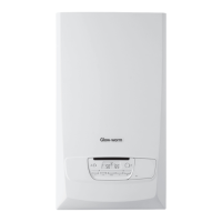
15.1.1 Check the electrical installation
24
V
V
4
1
Key
1 Main board
2 Neutral
3 Live
4 Multimeter
• Remove the front casing panel
• Check the external electrical supply to the boiler is on and a
supply of 230V is present at the ‘L’ and ‘N’ terminals on the
main board.
• Check the electrical installation and appliance, carry out tests
for earth continuity, polarity, short circuit and resistance to
earth, using a suitable multimeter.
• Bare metal points such as screws or rivets will act as suitable
earth check points on the appliance.
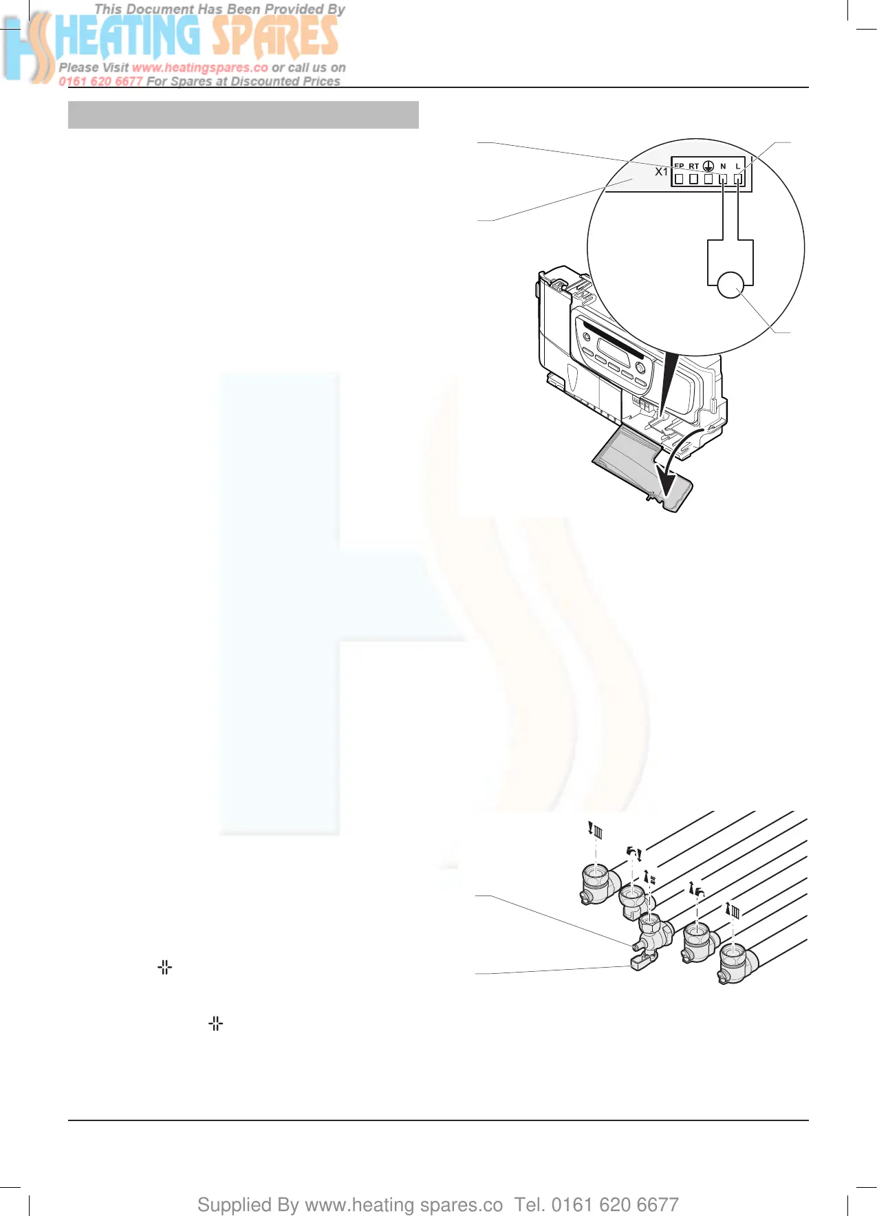
15.1.2 Check the gas supply
1
2
Key
1 Gas service isolation valve
2 Test point
• Check that there is a gas supply to the boiler and the gas
service isolation valve is turned on.
• Check pressure at the gas service isolation valve.
MAINTENANCE
 Loading...


