Supplied By www.heating spares.co Tel. 0161 620 6677
0020085231_02 - 05/10 - Glow-worm
- 41 -
1
2
3
2B
2A
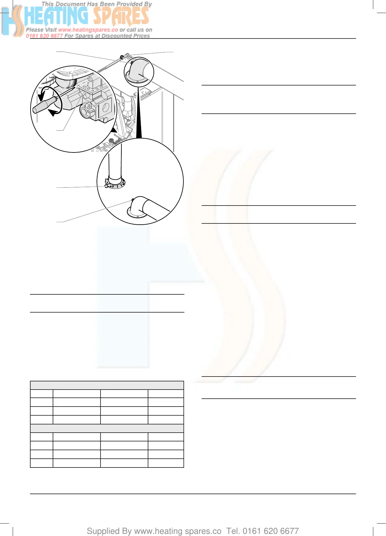
Key
1 Throttle
2 Combustion analyser sample point
2A Flueelbow
2B Verticalueadaptor
3 Cap
18.3.3 Maximum rate check and adjustment
i
To verify the maximum gas rate CO2 setting the
appliance must be checked at the maximum rate.
• Activate the test mode "P.01" and set the value to 100 in
order to force the burner at P. max. See chapter "Specic
adjustment ► Appliance technical settings and parameter list
► Test modes".
• Wait approximately 5 minutes to read a stabilised CO2 value.
• Check that the value is within the range specied in table in
the “check” column.
G20 Burner % CO2
Model Check (case on) Setting (case off) CO/CO2 ratio
24cxi
9.2 ± 0.3% 9 ± 0.2% 0.004
30cxi
9.2 ± 0.3% 9 ± 0.2% 0.004
35cxi
9.2 ± 0.3% 9 ± 0.2% 0.004
G31 Burner % CO2
Model Check (case on) Setting (case off) CO/CO2 ratio
24cxi
10.3 ± 0.3% 10.1 ± 0.2% 0.004
30cxi
10.3 ± 0.3% 10.1 ± 0.2% 0.004
35cxi
10.3 ± 0.3% 10.1 ± 0.2% 0.004
If the combustion reading is not within the acceptable values
and the integrity of the complete ue system and combustion
circuit seals have been veried and the inlet gas pressure (and
gas rate) have been veried, then, it will necessary to adjust the
combustion rate of the appliance.
i
Adjustment is made by turning the throttle an ⅛
of a turn, waiting 1 minute to allow the appliance
to stabilise before checking or making further
adjustments.
• Remove the sticker covering the “throttle” adjustment screw,
if tted.
• Rotate the “throttle” (1) (anti-clockwise to increase), to the
required CO2, refer to previous diagram and the “Setting”
column in the table.
• When you have nished, press the On/Off button to exit the
test modes.
• Remove the analyser probe and replace the cap on the
sampling point, replace the controls fascia, and the front
casing panel.
i
Remember to replace the sample point cap on
completion of the test.
18.3.4 Gas rate check
• Check the gas rates as described in the commissioning
section.
18.3.5 Completion
If it is not possible to achieve the required results for either the
combustion or gas rates, it will be necessary to complete a full
service of the appliance and then repeat the combustion check
procedure.
If after servicing and adjustment of the appliance the
combustion values are still unacceptable and after further
remedial work has been carried out, the appliance must be
disconnected until the CO/CO2 ratio is acceptable.
• Advice can be sought from the Glow-worm Technical
Helpline.
18.4 Servicing
i
If the Combustion CO2, CO/CO2 ratio & Gas rate
checks did not require adjustment then it will not be
necessary to complete a full service.
All routine servicing requirements can be achieved by the
removal of the front panel.
• Position the control box into the service position.
• Before commencing with a service or replacement of parts,
isolate the boiler from the electrical and gas supplies.
18.4.1 Service interval record
• Refer to benchmark book stapled in the centre pages of this
manual.
MAINTENANCE
 Loading...


