Supplied By www.heating spares.co Tel. 0161 620 6677
0020085231_02 - 05/10 - Glow-worm
- 14 -
8 Hydraulic connection
8.1 Gasandwaterconnections
The whole of the gas installation, including the meter, should
be inspected, tested for tightness and purged in accordance
with the current issue of BS6891 and in IE the current edition of
I.S.813 “Domestic Gas Installations”.
i
The appliance may contain a small amount of water,
place a water container beneath the boiler connections.
• Take care to clean the pipes before assembly removing any
debris or burrs. Grease and oils may need to be removed
they are not possible to remove by cleansing and ushing.
Foreign bodies in the system may enter the appliance and
interrupt its operation.
• Do not use any solvent products, due to the risk of damaging
the circuit.
a
Do not perform any 'hot work' directly under
the appliance, this may cause damage to the
appliance base. Heat may also damage the
isolation valves.
Always pre-assemble pipes before tting them to
the boiler.
• Only use original seals supplied with the appliance.
• Check that there are no leaks. Repair if necessary.
1
2
3
4
5
6
7
6
Key
1 Heatingreturnisolatingvalve+sealingwasher¾"
2 Coldwaterinletisolatingvalve+sealingwasher¾"
3 Gasserviceisolatingvalvewithpressuretestpoint+sealing
washer½"
4 Domestichotwateroutletisolatingvalve+sealingwasher¾"
5 Heatingowisolatingvalve+sealingwasher¾"
6 ConnectionØO.D.22mm
7 ConnectionØO.D.15mm
• Remove the protective caps from the boiler connections.
• Flush out the domestic hot water and the heating systems.
i
Before turning on the cold mains supply to the boiler
turn off the cold water inlet to the boiler, lock the lling
loop in the closed position and close its lling taps.
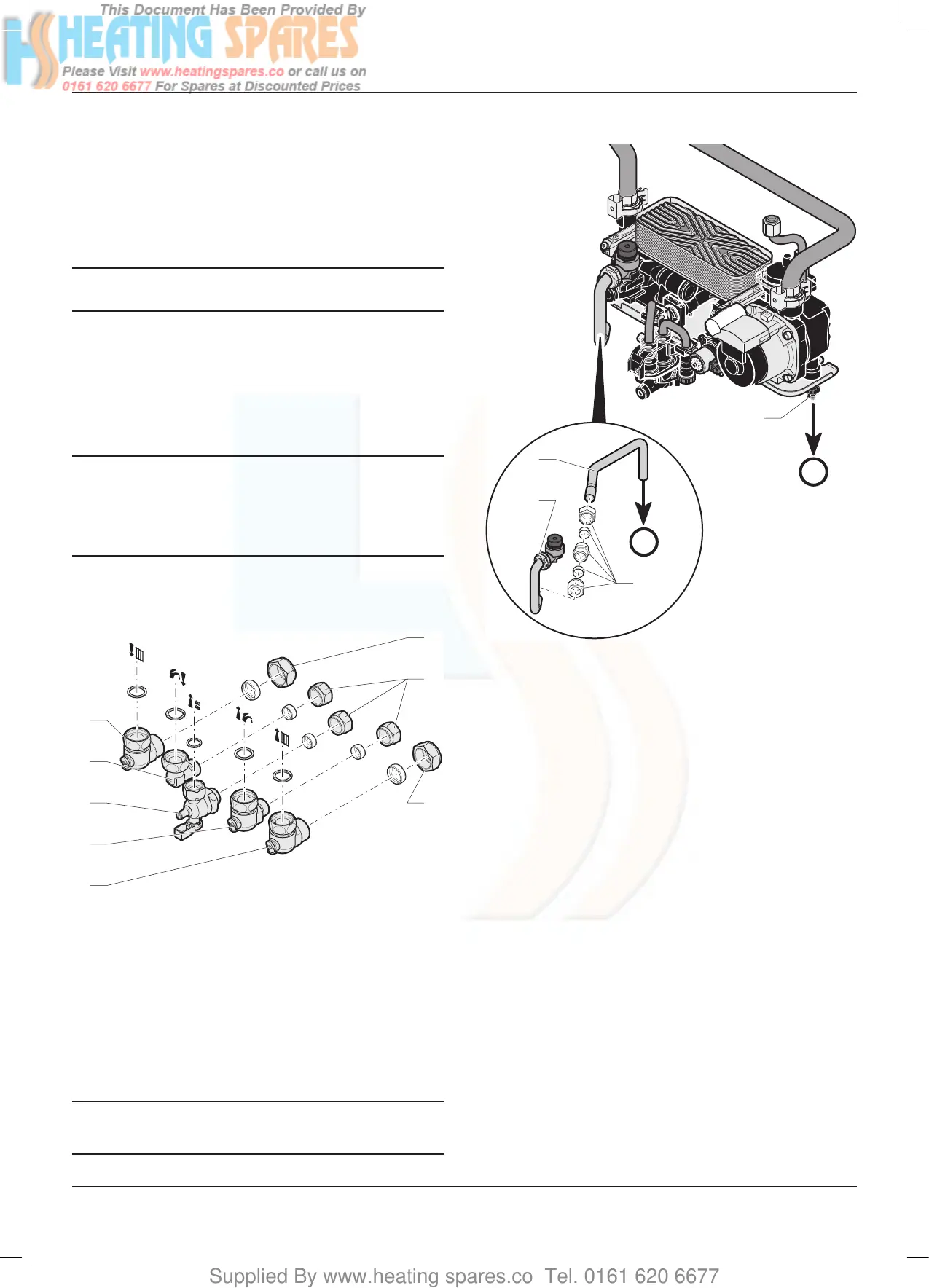
8.2 Safety Discharge Valve
B
A
3
4
2
1
Key
1 Compressiontting
2 PRV pipe
3 Pipe for PRV
4 Draining outlet
A PRV outlet - to outside
B Appliance drain tap
This must be extended, using not less than 15mm o.d. pipe,
to discharge, in a visible position, outside the building, facing
downwards, preferably over a drain.
To ease future servicing it is advisable to use a compression
type tting to extend the safety discharge valve tube.
The pipe must have a continuous fall and be routed to a
position so that any discharge of water, possibly boiling,
or steam cannot create any danger to persons, damage to
property or external electrical components and wiring.
INSTALLATION

 Loading...


