Supplied By www.heating spares.co Tel. 0161 620 6677
0020085231_02 - 05/10 - Glow-worm
- 13 -
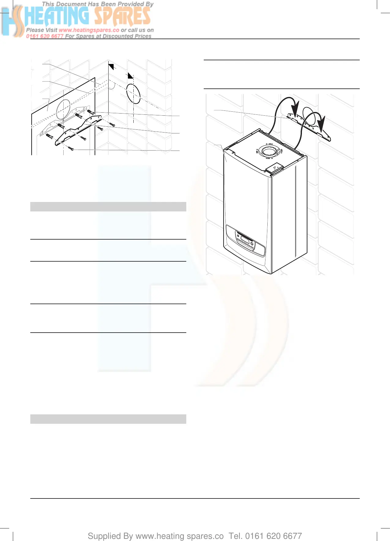
7.4.1 Fixingtothewall
130
90°
4
5
6
2
1
3
Key
1 Wall template
2 Standarduelengthhorizontal
3 2.5°44mm/metreinclinedextendeduelength
4 Wall plug
5 Hanging bracket
6 Screw(notsupplied)
Flue hole cutting
• Mark the position of the ue centre.
• Remove the wall template, then drilling the ue hole.
i
The ue is designed with an internal fall of 44mm/
metre (2.5
o
), therefore the hole can be drilled
horizontally.
• Use a 105mm diameter core drill for external access ue
installation (60/100 ue) (80/125 ue ► Ø130mm).
• Use a 125mm diameter core drill for internal access only ue
installation (60/100 ue) (80/125 ue ► Ø150mm).
i
If ue extension pipes are to be used then a core
drill size of 125mm is required. This will allow the
extension pieces to slope at 44mm/metre (2.5
o
)
towards the boiler.
• If tting a side ue, extend the ue centre line into the corner
then 130mm along the adjacent wall.
• If tting an extended side ue, determine the ue hole centre
by extending the dashed inclined line on the template to the
side wall. This dashed line is drawn at 44mm/metre (2.5
o
)
rise from the boiler. Where this line reaches the side wall, a
horizontal line should be marked. The vertical centre line of
the ue should then be marked at 130mm from the back wall.
To allow for the ue passing through the wall at this angle
a 125mm hole should be drilled irrespective of internal or
external installation.
Hanging bracket xing
Due to the varied site conditions, xings are not supplied and
advise that the installer should supply those which are suitable.
• Drill the holes for the xing screws in accordance with the
wall template.
• Fix the hanging bracket on the wall.
7.4.2 Boiler hanging
a
With regards to the Manual Handling Operations,
1992 Regulations, the following lift operation
exceeds the recommended weight for a one
person lift, refer to chapter "Manual Handling".
2
1
Key
1 Boiler
2 Hanging bracket
• Lifting the boiler into position, lean the top of the boiler
slightly to the wall and position just above the hanging
bracket.
• Lower the boiler slowly and engage onto the hanging bracket
INSTALLATION

 Loading...


