Supplied By www.heating spares.co Tel. 0161 620 6677
0020085231_02 - 05/10 - Glow-worm
- 23 -
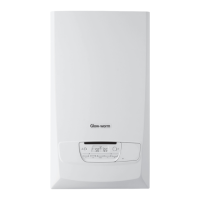
11.3.2 230V permanent supply + 230V system
controls
a
All cables connected to the appliance should be
permanently xed to the wall.
i
This appliance will not operate without a link or
system controls tted.
24
V
4
5
6
7
2
1
Key
1 230V permanent supply
2 System controls
3 Frost stat
4 Main board terminal block
FP=Froststat230V(switchable)
RT=Switchlive(230V)
= Mains earth
N = Mains neutral
L = Mains live
5 Junction box
6 Fuse
7 Double pole connector
• Connect the mains supply and system heating controls e.g.
room thermostat as described.
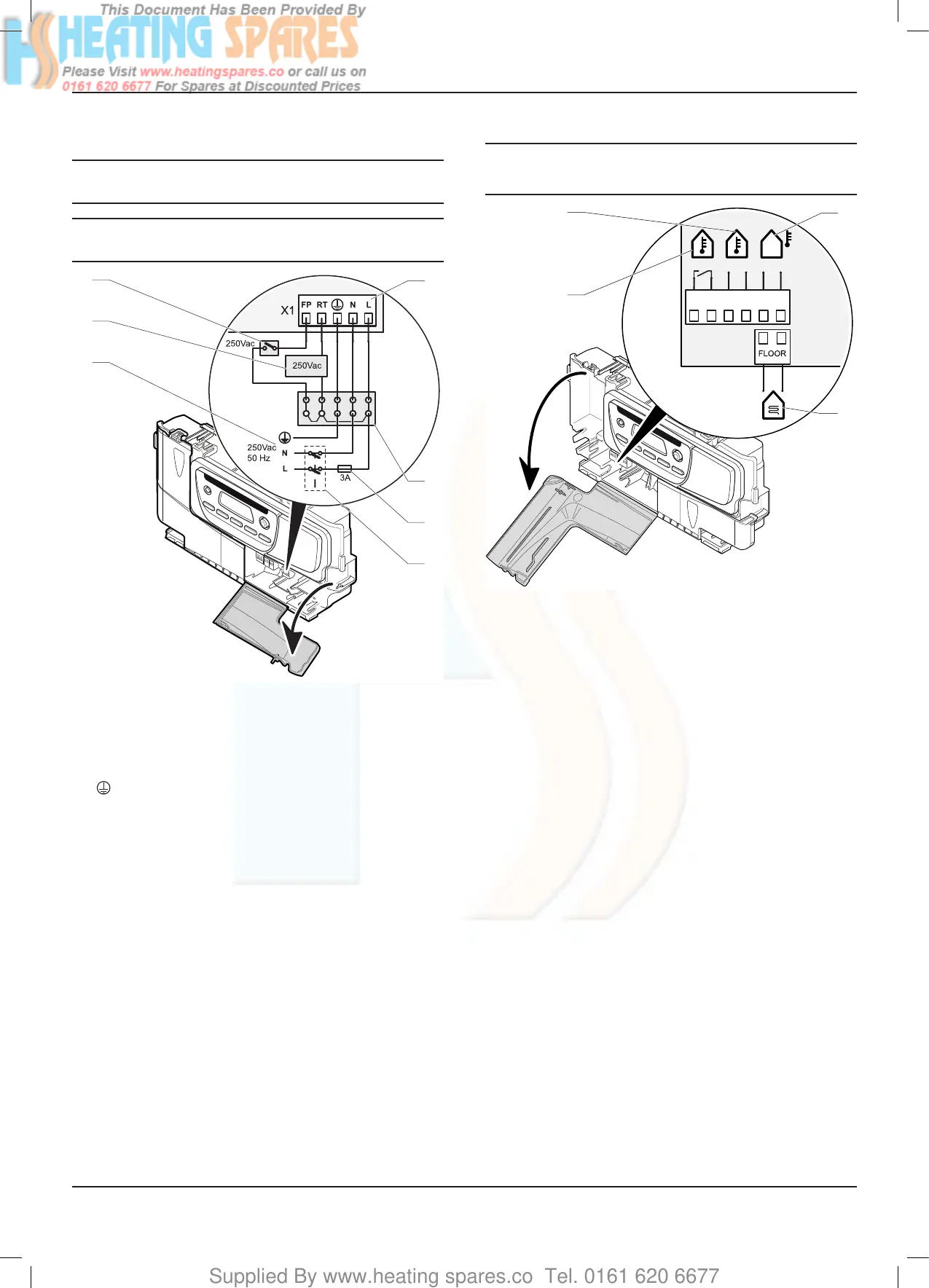
11.4 External accessories
e
Under no circumstances must any mains voltage
be applied to any of the terminals on the 24v
connection plug.
230
V
X17
X18
RT 24V T° extBUS
BUS
24 V
3
4
1
Key
1 24V room thermostat connector
2 Ebus room thermostat connector or Ebus radio receiver
3 Outdoor sensor connector
4 Overheatingsafetyconnectorforheatingoor
• Fit external controls in accordance with the rules in force.
11.5 Testing the electrical connections
Carry out preliminary electrical system checks as below:
• Resistance to earth (<1 Ohm)
• Short circuit test (L-N)
• Resistance to earth (L-E)
• Polarity check
INSTALLATION
 Loading...


