Glow T180
Tankless Condensing Water Heater
34
3.6.2 Tankless Water Heater Isolation
Valve Kit
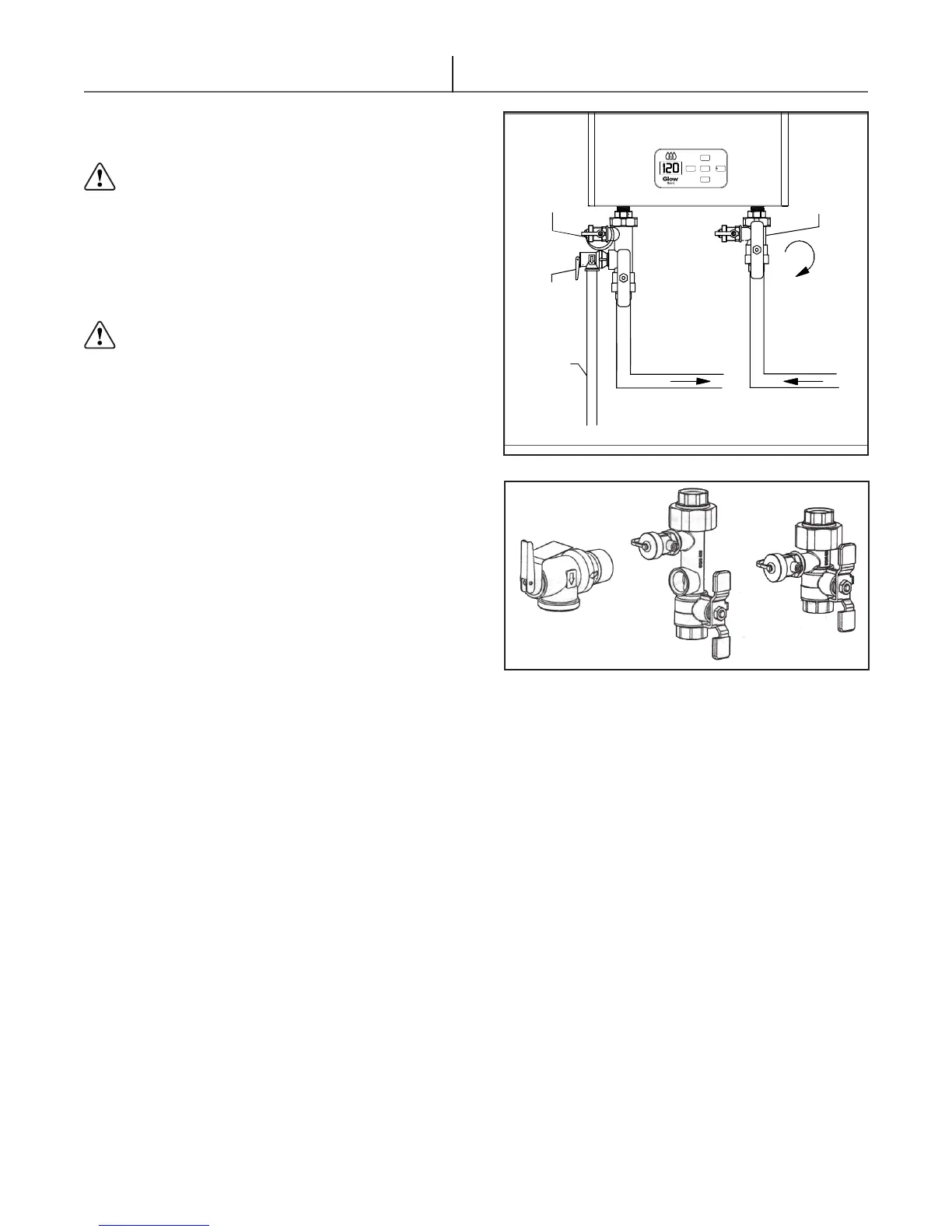
An optional Tankless Water Heater Isolation
Valve Kit (g. 3.16) is intended for installation
onto tankless water heater cold inlet and hot
outlet connections. Each assembly features union
connections, full-port, positive-shutoff ball valve
design and integral drain valves with capped hose
thread connections. They are available with 3/4” FIP
cold inlet and hot outlet connections.
Isolation valves should be installed on the
water heater. This will facilitate all maintenance and
service operations when the water heater needs to
be serviced.
Remove the COLD water isolation inlet valve
assembly (identied by the blue handle) from the
packaging. Disassemble the union connection by
loosening the union nut and removing the tail piece
and gasket. Ensure that all components are present:
3/4” NPT tail piece, gasket, union nut and steel
nut retaining ring (installed onto the valve’s body).
NOTE: The union nut is permanently mounted to the
valve assembly.
Connect the valve assembly’s 3/4” NPT to the piping
cold water supply line. Use Teon tape on the pipe
nipple’s external threads. Use the appropriate ux
and solder and verify that the isolation valve is in
the open position before sweating onto the copper
tubing. Make sure to position the valve assembly
in such a way that the handle and purge valve
stem are accessible and can be operated without
obstruction. Typically, this results in the drain valves
capped hose threads facing outward toward the user
or to the left, for the COLD isolation valve or right, for
the HOT isolation valve.
Use the appropriate thread sealer (Teon tape),
thread and tighten the 3/4” NPT tail piece onto the
water heater’s COLD water inlet.
Verify that the gasket is centrally positioned onto
the tail piece. Reconnect the union nut to the now-
installed tail piece. Using the appropriate wrenches,
brace the tail piece and tighten the union nut.
Remove the HOT water isolation outlet valve
assembly (identied by the red handle) and the
pressure relief valve from the packaging. Apply
Teon tape to the male threads of the pressure
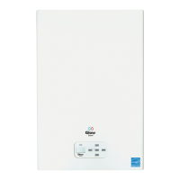
Figure 3.16 - Optional Service Kit
Figure 3.17 - Pressure Relief Valve and Isolation Valves
NOTE: Must be rated for water heater use. The relief valve
must have a rating capacity of 500,000 BTU/H and 150/PSI
pressure rating.
Glow T180
MENU
UP
ENTER
DOWN
RESET
OVER
FLOW
TUBE
PRESSURE
RELIEF
VALVE
COLD
WATER
VALVE
HOT
WATER
VALVE
ROTATE
CLOCKWISE
FOR SERVICE
DOMESTIC HOT
WATER OUT
DOMESTIC COLD
WATER IN
relief valve. In accordance with the water heater
manufacturer’s or local code requirements, install
and tighten the pressure relief valve into the 3/4”
female NPT connection located next to the drain
valve. Position the outlet of the pressure relief valve
downward.
Repeat the above procedures to install the HOT
water isolation outlet valve assembly onto the hot
water outlet connection of the water heater.