Glow T180
Tankless Condensing Water Heater
52
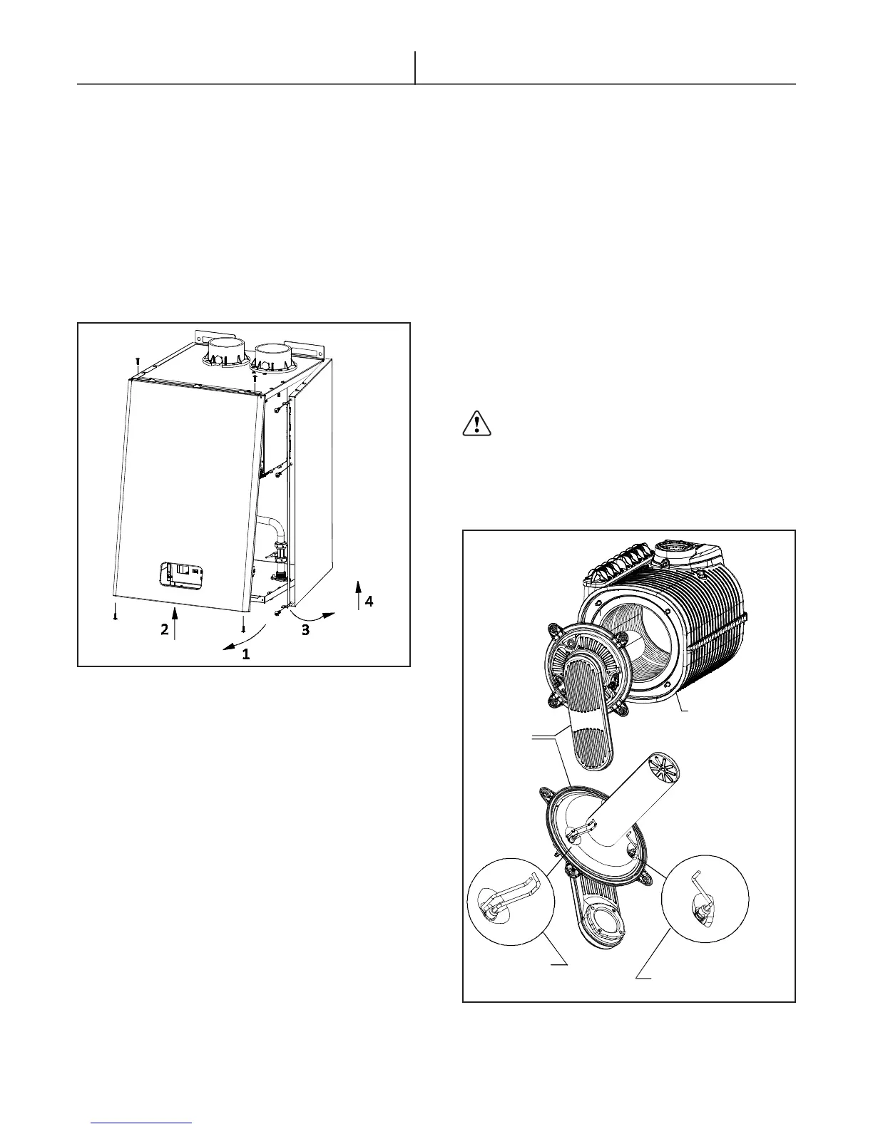
BURNER
ASSEMBLY
IGNITION
ELECTRODE
HEAT
EXCHANGER
IONIZATION
ELECTRODE
(FLAME SENSOR)
Figure 5.3 - Water heater burner assembly and heat exchanger
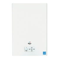
5.5 Accessing The Water Heater
All maintenance operations may require one or more
of the water heater casing panels to be removed.
The side panels can only be removed after the front
panel has been removed. (see g. 5.2)
Front panel:
Δ Remove the 4 xing screws at the top and
bottom of the front panel.
Δ Grasp the lower part of the panel and pull it
outwards and then upwards.
Left and right side panel:
Δ Remove the xing screws at the edge of the side
panel.
Δ Grasp the bottom of the panel, move it sideways
and then upwards to remove it.
To access the electrical connections of the ignition
control board and the main control board, proceed
as follows:
Ignition Control Board
Δ Remove the front panel.
Δ Remove the 2 xing screws on the top front of
the right panel
Δ Remove the 2 xing screws on the top of the
shell.
Δ The ignition board and bracket can now be
removed by pulling it towards the front.
Figure 5.2 - Water heater access panels
Display Control Board
Δ Remove the front panel.
Δ Unscrew the four xing screws and remove the
cover.
Draining the hot water system
If there is a danger of freezing, the hot water system
should be drained. This can be done as follows:
Δ Close the main water supply valve.
Δ Open all the hot and cold water taps.
Δ On completion, close all the previously opened
taps.
5.6 Maintenance Operations
5.6.1 General Information
Before carrying out any cleaning or
part replacement operations, ALWAYS turn
off the ELECTRICITY, WATER and GAS
SUPPLY to the water heater.