Glow T180
Tankless Condensing Water Heater
47
4.5 Starting Up The Water Heater
Once the system has been lled, proceed as follows:
Δ Check that the exhaust ue is free of
obstructions and correctly connected to the
water heater.
Δ Plug the power cord of the water heater into
the wall receptacle and make certain the unit is
operational.
Δ Open the gas cock supplying the unit.
Δ Create a call for hot water by opening a hot
water faucet; The faucet icon will start to ash
and a ame icon will appear.
Δ The automatic ignition system will attempt to
light the burner. This operation is repeated
for 3 times. It may be necessary to repeat the
operation in order to eliminate all the air from
the gas line. To repeat the operation, wait
approximately three minutes before reattempting
to light the water heater. To reset the water
heater, press the [RESET] button and hold for 3
seconds then release.
4.6 Gas Valve And Set Up
This water heater has been set up from the factory
for normal operation, however it is required to
complete a system check of the components and
preform a combustion analysis prior to completing
the installation. The system check consists of the
following:
Δ Check and measure the gas pressure available
from the source. 7” w.c. is the nominal pressure
required for (NG), 11”w.c. (LP).
Δ Check and ensure that 120v is available at the
outlet
Δ Check for correct polarity
Δ Ensure the hot and cold water supplies are
piped correctly to the water heater.
Δ Ensure the relief tube is piped to the pressure
relief valve and the condensate hose is to a
drain
Δ Either a service valve kit or a tee and relief valve
is to be installed on the water heater
Δ Once the unit has be plugged in, verify that all
safety devises are operational (hi limit switch,
micro fuse, blocked ue sensor, see Section 5.5)
Δ Once a demand for hot water is made, sounds
emitted from the heat exchanger are normal
until all air has been eliminated from the heat
exchanger
Δ The water heater must be operating at maximum
capacity in order to complete a combustion
analysis (see adjusting the throttle).
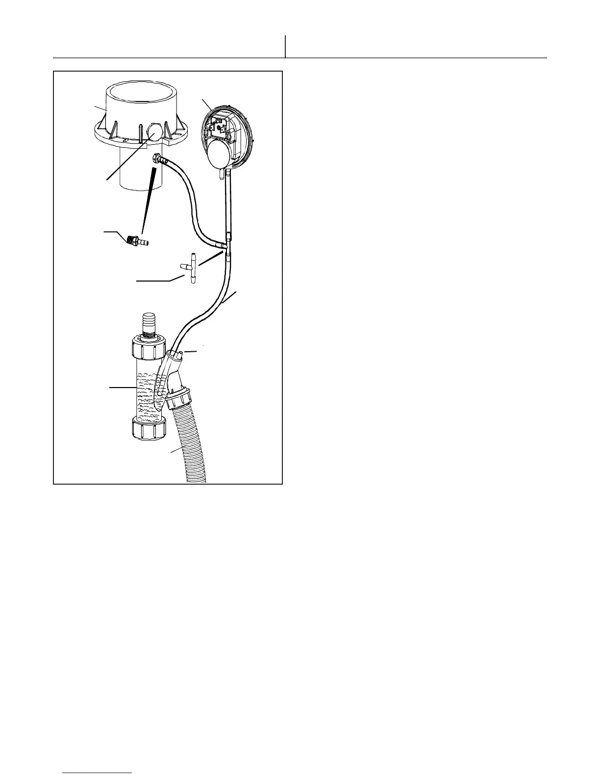
Figure 4.1 - Condensate trap connections
3/16”
SILICONE
HOSE
PLUG
1” CONDENSATE
HOSE
CONDENSATION
TRAP
BARB
FITTING
COMBUSTION
ANALYZER
PORT
EXHAUST
ADAPTER
BLOCK VENT
SWITCH
HOSE
CONNECTING
TEE