Glow T180
Tankless Condensing Water Heater
33
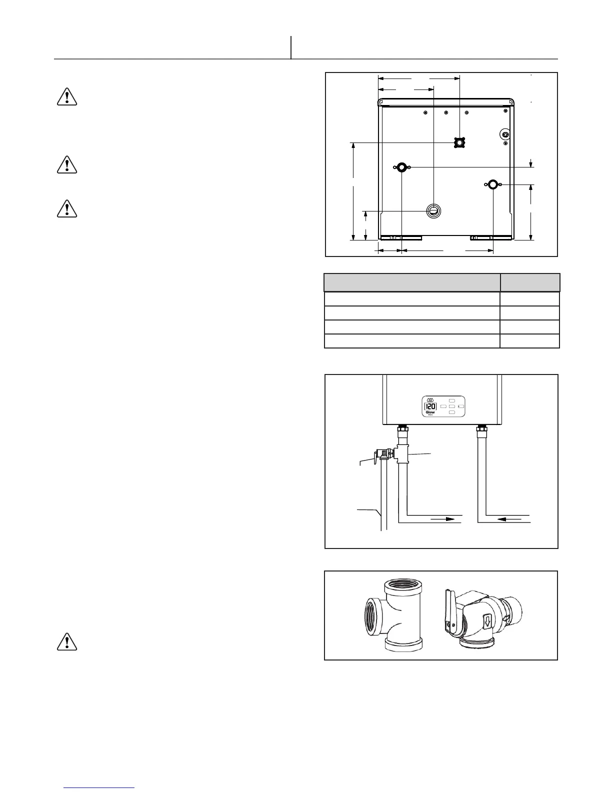
3.6 Water Connections
In order to safeguard the heat exchanger,
especially in case of water heater replacement, it
is recommended that the system is hot-ushed to
remove any impurities (especially oil and grease)
from the pipes.
Make sure the water pipes are not used
to ground the electrical system. The pipes are
unsuitable for this purpose.
A sediment inlet water screen is supplied and
already installed in every unit. Do not allow water to
ow into the unit unless the dirt inlet water screen is
in place. Serious irreparable damage can occur and
void the warranty.
3.6.1 Pressure Relief Valve And Tee
Operation and Maintenance Instructions
Should the installer choose not to use the isolation
valve kit, then a pressure relief valve and tee must be
used. Either kit is available from the manufacturer.
Installation
The Pressure Relief Valve and Tee must be installed
in place of the optional Tankless Water Heater
Isolation Valve Kits in accordance with local code
requirements. In the event that these instructions
conict with code requirements, the code shall take
precedence. (Figure 3.14 & 3.15)
Δ Install the forged brass tee onto the hot water
outlet of the water heater. The pressure relief
valve is to be tted into the branch port of the
tee. Be sure to use Teon tape or approved
thread sealer when tting the assembly together.
The outlet connection of the pressure relief valve
must face down.
Δ The appropriate 3/4” adapters can be tted to the
HOT and COLD water lines.
Δ A pressure relief valve, complying with the
Standard for Relief Valves and Automatic Gas
Shut-Off Devices for Hot Water Supply Systems,
ANSI Z21.22/CSA 4.4, must be installed at the
HOT water outlet connection of the water heater
during installation. Local codes shall govern the
installation of any relief valve.
IMPORTANT – Anti scald mixing valve
must be installed and as per local codes and
authorities.
INLET
HOT WATER
OUTLET
GAS INLET
COLD WATER
CONDENSATE OUTLET
6.8
3.5
Figure 3.15 - Tee and Pressure Relief Valve
NOTE: Must be rated for water heater use. The relief valve
must have a rating capacity of 500,000 BTU/H and 150/PSI
pressure rating. The drawing illustrates a pressure-only relief
valve.
Figure 3.13 - Water Heater Connections (inches)
Figure 3.14 - Relief Valve Installation
PRESSURE
RELIEF
VALVE
TEE
OVER
FLOW
TUBE
TO DRAIN
DOMESTIC HOT
WATER OUT
DOMESTIC COLD
WATER IN
Glow T180
MENU
UP
ENTER
DOWN
RESET
Cold Water Inlet 3/4” NPT
Hot Water Outlet 3/4” NPT
Gas Connection 3/4” NPT
Condensate Outlet 1”
Connection
Size
Table 3.2