Glow T180
Tankless Condensing Water Heater
54
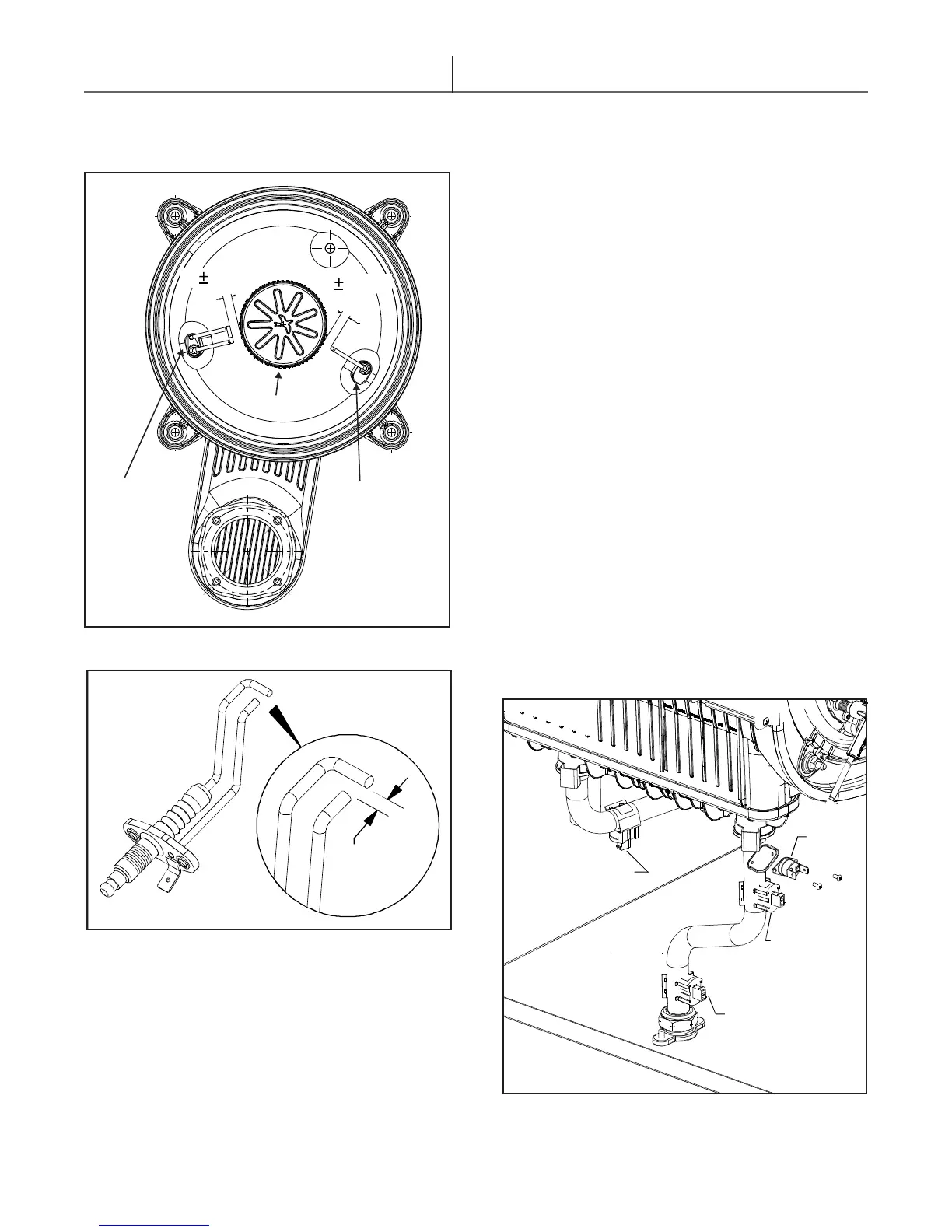
INLET TEMPERATURE
SENSOR
DHW SENSOR
HI-LIMIT
SWITCH
HEAT EXCHANGER
OUTLET SENSOR
Figure 5.7 - Water heater sensors
Δ Check for continuity between the two leads. If
there is no continuity replace the switch.
Δ Unscrew the xing screws and remove the high
limit switch.
Δ Replace the high limit switch and re-assemble
the components following the above procedure
in reverse order.
Δ Switch on the electricity, water and gas supplies
and restart the appliance.
5.6.4 Water Sensors (see Figure 5.7)
Δ Make certain the sensor is properly secured in
place and making good contact with the water
pipe.
Δ Un-Plug the connecting wire.
Δ Disconnect the wire leads of the domestic
sensor. Set the multimeter to read Ohm’s and
apply the multimeter terminals to the sensor
leads. You should have a value of “Nominal
resistance at 25°C / 77°F – 10,000 Ohm”. If the
sensor does not provide the right data, as per
the table, the sensor is out of calibration and
needs to be replaced. (see section 7.10)
Δ Replace the sensor and re-assemble the
components following the above procedure in
reverse order.
Δ Switch on the electricity, water and gas supplies,
open the shut-off valves and ll the central
heating circuit. Then restart the appliance.
5.6.3 High Limit Switch (Figure 5.7)
This high limit switch opens when the
temperature in the loop exceeds 95°C. A
manual reset of the unit is required.
Δ Disconnect the voltage.
Δ Un-plug the electrode wires.
4.5 MM
(0.180”)
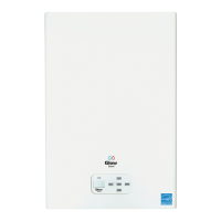
Figure 5.6 - Water heater electrode gap
Figure 5.5 - Electrodes distance from the burner
When inspecting the ignition electrode, a
4.5mm gap should be present between the
grounding rod and the ignition electrode.
8 1mm
8 1mm
IGNITION
ELECTRODE
BURNER
IONIZATION
ELECTRODE