SmartBox
®
4 / SmartBox
®
4 PRO
14 / 28 part no. 28 400 57 d
Tanks
SmartBox
4 Pro
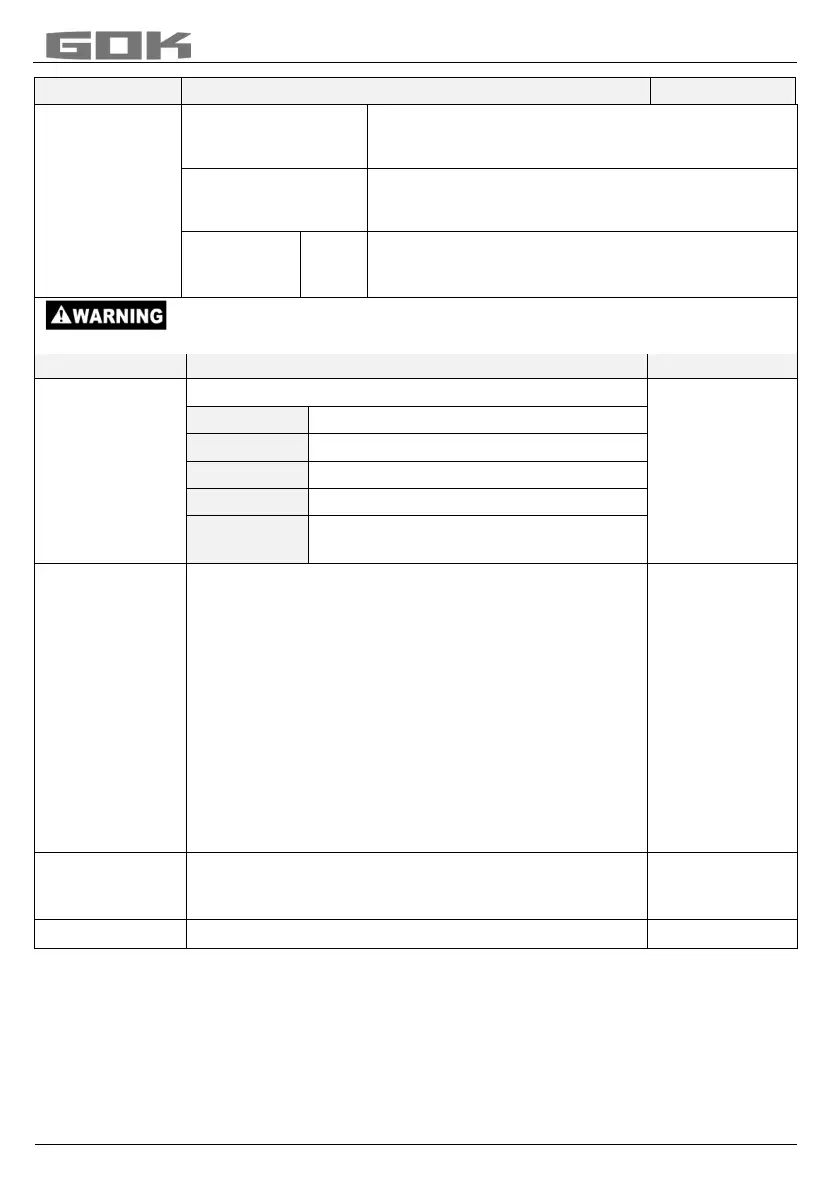
cyclically one after the other, with L, % and, if
applicable, temperature. With display change.
The (eg. L) values of tanks 1 to 4 are displayed
(depending on the number of connected probes)
No
values (eg. in L) Tank 1 – 4
total capacity display + percent values
Entering incorrect switching points and mixing up the switch-on and shut-off
point can lead to the overfilling of the tank or the dry running of a pump!
SmartBox 4
The relay does not switch.
Forces the relay to energise.
Forces the relay to de-energise.
When the relay switches over a
message is output
Example of switch point setting for Active (with
hysteresis):
Enter switching points as % values from 01 - 99 (and/or
enter as °C value from -99 to +99 only for probe with
temperature measurement)
deactive activate with [+] / [-] to
active press [Enter] to confirm
On 10% ON: set with [+] / [-] [Enter]
Off 12% OFF: set with [+] / [-] [Enter]
On +0°C ON: set with [+] / [-] [Enter]
Off +0°C OFF: set with [+] / [-] [Enter]
Deactivate the relay via deactive or input of 0% or
ON ______%
OFF ______%
ON ______°C
OFF ______°C
SmartBox 4
Press [Enter] to return to display mode
Press [Enter] to return to display mode
After performing entry steps 1 - 7, the programming process is completed.
After confirmation of step “8.Exit“, the device automatically returns to default display mode;
the current tank content is shown in the display.
Special functions are available under entry steps 9 to 24.
After the end of setup, do not forget to replace the housing cover!
After completing the ASSEMBLY and PROGRAMMING, carrying out a function check is
recommended (FUNCTION CHECK section).