16
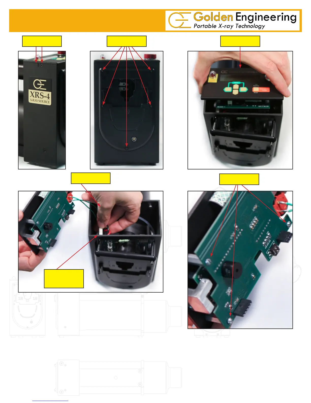
8.0 INSTRUCTIONS FOR REPAIR
STEP 4
STEP 1 STEP 2 STEP 3
KEY SWITCH
CONNECTOR
STEP 5
Counter Board
FUSE REPLACEMENT Requires T-10 Torx driver & needle nose pliers.
1. Remove the back plate. Remove the 5 screws in the back
plate then pull the back plate off slowly maneuvering the
battery terminal connecting wires through the opening in the
oscillator board.
2. The 20 amp fuse is the white one inch long fuse on the left side of the oscillator board. The 15 amp fuse
is a small green fuse in the center of the oscillator board. The 15 amp fuse is soldered in place and can
only be replaced using a soldering iron.
3. REMOVING THE BOARDS Refer to the diagram on page 17
4. Using T10 Torx Remove the 2 screws on both sides of the housing.
5. Using T10 Torx Remove the 5 screws holding the back plate in place.
3. Lift the top plate from the control module.
 Loading...