17
INSTRUCTIONS FOR BATTERY DISPOSAL Follow all federal, state, and local laws for disposal of lithium-ion
batteries. Batteries may be returned to Golden Engineering.
4. Disconnect the Key Switch wires from the Oscillator Board.
5. Use at head driver to remove screws holding the Counter Board in place and remove the Counter Board.
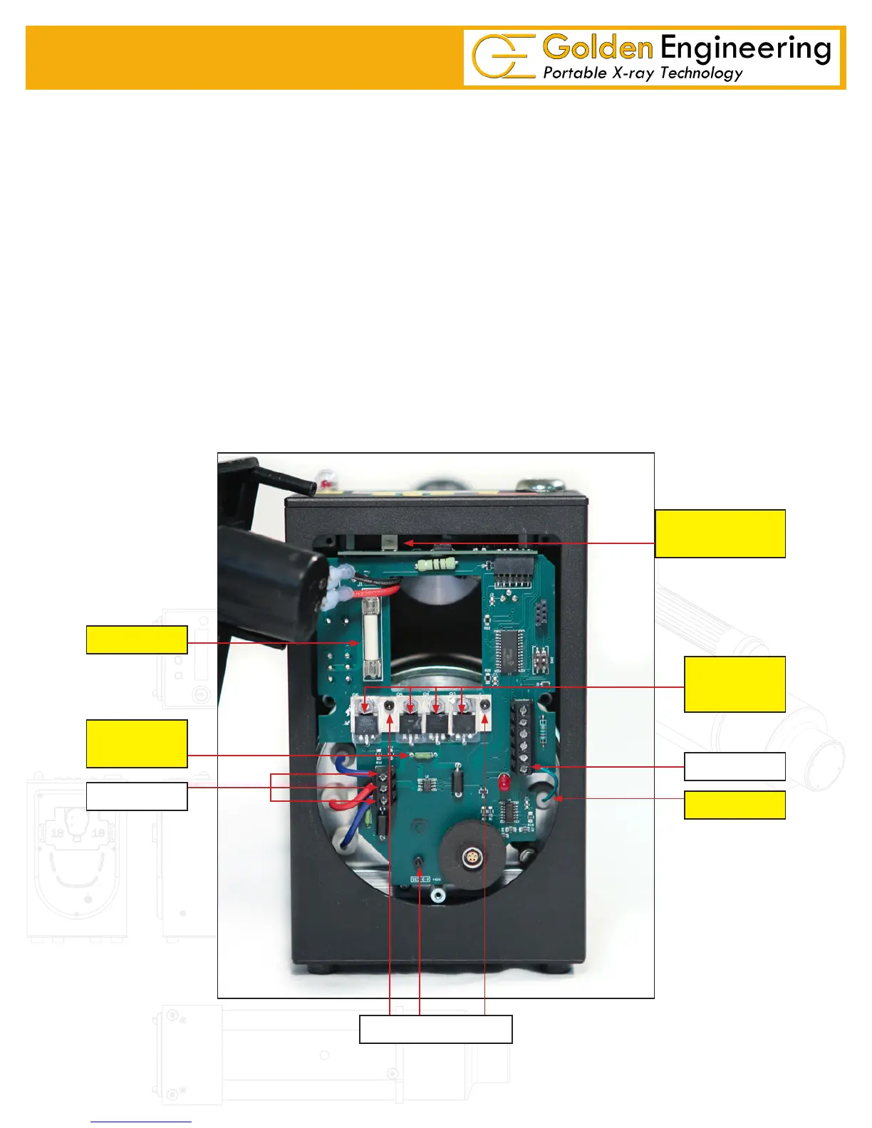
6. There are three terminals on the lower left side of the Oscillator Board and one on the lower right.
Disconnect the two blue wires, one red wire, and one green signal wire using Philips driver.
7. There are three socket head cap screws holding the oscillator board in place. Two are in the middle of
the board and one is at the bottom. Remove these three screws then remove the Oscillator Board.
BOARD INSTALLATION
1. Install the Oscillator Board.
2. Put the three cap screws through the oscillator board and then put the ½” offsets on the back of the screws.
3. Attached the two blue feedback wires, one red feedback wire, and green signal line.
4. Attach the Counter Board to the top plate.
5. Attached key switch wires to the Oscillator board.
6. Set top plate back in place making sure Counter Board and Oscillator Board connect.
7. Reinstall the back plate.
8. Insert and tight the two screws on each side of the control module.
20 AMP
15 AMP
FUSE
STEP 6
STEP 7
POWER
TRANSISTOR
SIGNAL WIRE
STEP 6
Oscillator Board
LCD CONTRAST
ADJUSTMENT
 Loading...