23
02 Installation Instructions User Manual V1.6-2022-01-05
Step 1
TerminalCable
Case1. If there is no 240V Load, both 120V Load 1 and Load 2 individually have a total Max power
≤ 5kVA.
Case2. If there is only a 240V Load and no 120V loads, inverter output power ≤ 10kVA.
Case3. If there is 240V Load with a power draw = P1, then any 120V load has a maximum power
≤ (10-P1)/2 kVA.
Note:
The 120V and 240V load conguration of the auto-transformer should meet the below
requirements. It is stipulated that the 120V load received by L1-N and L2-N do not exceed 5kW
respectively. If there is a 240V load, 240V load power needs to be subtracted and distributed
equally. For example, 240V load power is P1, then (10kw-P1) / 2 is the remaining 120V power of
the L1-N and L2-N back-up circuits. The imbalance load cannot exceed the new power distribution.
L1-N: AC power provided between L1 leg and Neutral line
L2-N: AC power provided between L2 leg and Neutral line
Back-up wiring connection process
To reduce the risk of re, do not connect the wires to an AC load center
or circuit breaker panel which have too many cables connected.
Pour réduire le risque d’incendie, ne vous connectez pas à un centre de
chargement AC (panneau de disjoncteur) ayant des circuits de branche
multi-l connectés.
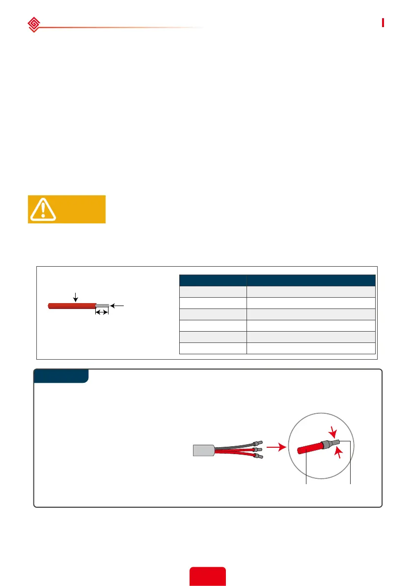
The maximum back-up current is 40A. Please use 90°C wire, 8-10AWG copper.
Do not use aluminum cables .
10AWG
10AWG
8AWG
8AWG
8AWG
8AWG
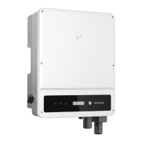
Use the correct wire ferrule from the accessory box. Crimp the ferrule onto the
conductor core tightly, as shown below.
Note:
Mak sure the cable jacket is not locked
within the wire ferrule's crimped
section. It is not necessary to utilize
a wire ferrule if using a solid (non-
stranded) conductor; just remove the
insulation.
Conductor
Core
Section
Maximum outside diameter
7.4mm(0.29in.)
18mm
0.71in.
Inverter Model
Conductor Core Section(Recommended)
WARNING!
GW5000A-ES
GW6000A-ES
GW7000A-ES
GW7600A-ES
GW8600A-ES
GW9600A-ES