31
02 Installation Instructions User Manual V1.6-2022-01-05
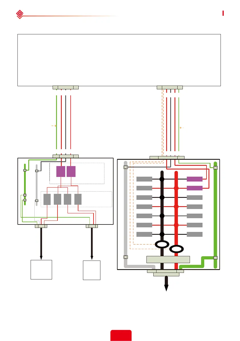
2.7 System Connection Diagram
Wiring Box Of AES Hybrid Inverter
BACKUP Loads
Distribution Panel
BACKUP Panel
Main Breaker
Neutral Bus-bar
BACKUP Panel
Loads Breakers
To BACKUP Loads
240V
BACKUP
Loads
120V
BACKUP
Loads
*Note 1
L1L2
N
To Utility Meter
Main Breaker
Main Distribution
Panel
1'' Conduit
1
'' Conduit
CB
CB
CB
CB
CB
CB
CB
50A CB
CB
CB
CB
CB
CB
50A CB
Two Meter CTs
Ground Bus-bar
*Note 2
CT1
CT2
*Note 3
PE
Note 1: The rated current of the circuit breaker depends on the load power.
Note 2: The Max continuous output current Per Phase @ 120 V is 40A.
Note 3: The back-up Output L1 or L2 Max continuous current carrying capacity≤40A.
AC BACKUP[L1,N,L2], 90℃, 8-10AWG
AC Grid[L1,N,L2], 90℃, 8-10AWG
Neutral Bus-bar
Ground Bus-bar
50A
CB
20A
CB
20A
CB
20A
CB
20A
CB
50A
CB
L1L2NPE
L1L2NPE
L1L2 N PE
L1L2 N PE