26
User Manual V1.6-2022-01-05 02 Installation Instructions
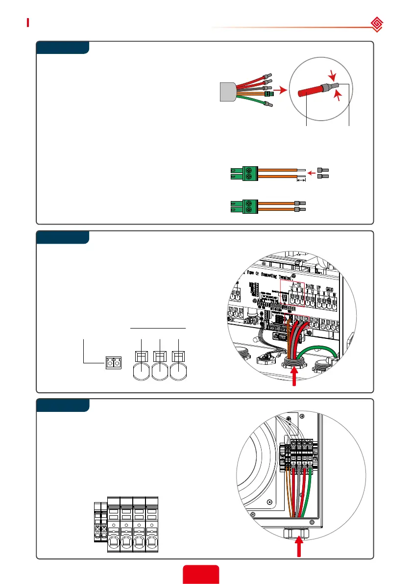
Step 3
NTC
L1Connect to auto-transformer
TX-NTC
N L2
A-TX
Step 4
7mm (0.28 in.)
Inverter side Auto-Transformer side
TerminalCable
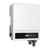
Step 5
L1
NTC
NTC
N
L2 PE
The temperature sensor (‘NTC’) connection to
the auto-transformer uses a pair of #22 or #24
AWG, 600V insulated wires. One end connects
with a 2-pin ‘A-TX’ terminal inside the inverter,
and the other end is crimped with the smallest
wire ferrule in the accessory box and connected
to the auto-transformer ‘NTC’ terminal.
Use the correct wire ferrule from the accessory
box. Crimp the wire ferrule onto each
conductor (L1, N, L2) core tightly.
Note:
Make sure the cable jacket is not locked
within the wire ferrule’s crimped section.
It is not necessary to utilize a wire
ferrule if using a solid (non-stranded)
conductor; just remove the insulation.
Run the NTC, power, and ground (PE)
wires through auto-transformer conduit.
Connect power conductors to the ATX
terminals (L1, N, L2). Connect the green
ground wire to the GND/PE terminal.
Connect the 2-Pin terminal to TXNTC.
Pass the A-TX (L1, N, L2), ground (PE), and NTC
wires through the auto-transformer conduit
entrance as pictured.
Secure the conduit tting.
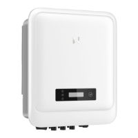
Run the wires to the auto-transformer port and
connect as shown.
After installation, secure the auto-transformer
cover with the 4 screws.