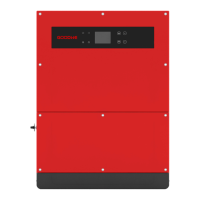
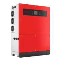
3.2 Inverter Overview
MT series inverter illustration.
Note: Image shown here is for reference only, actual product you receive may be different.
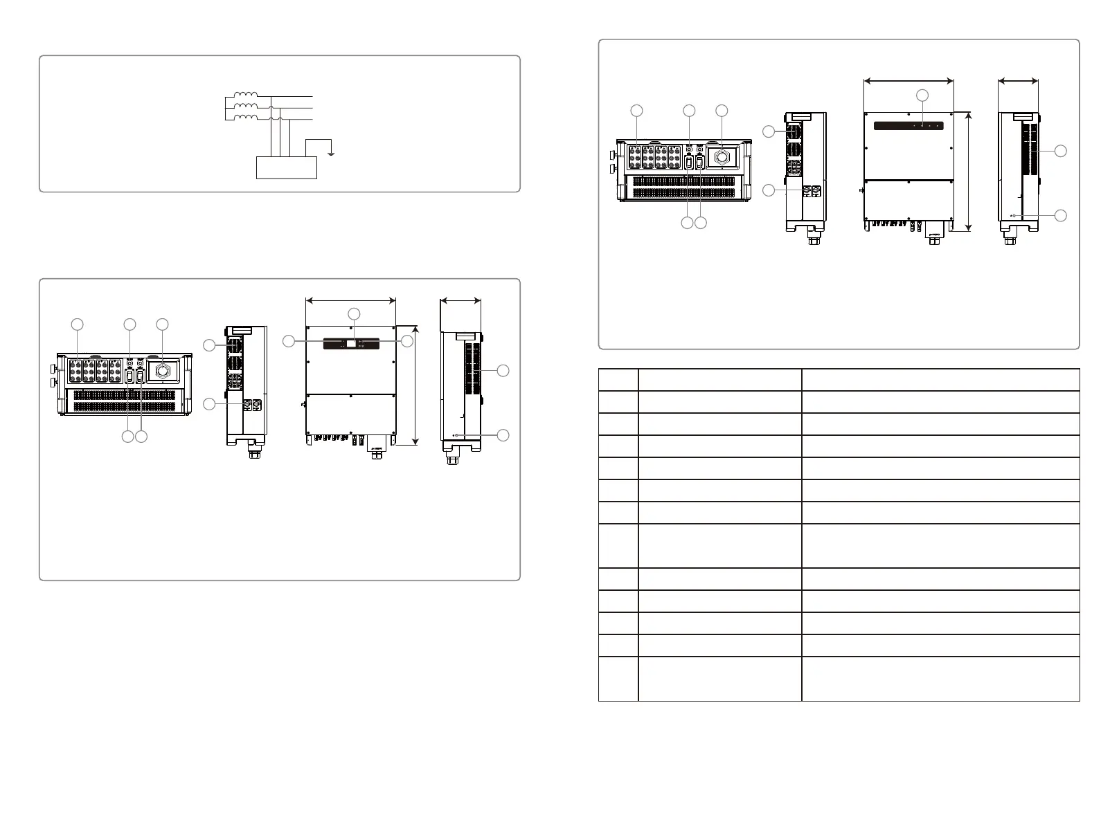
IT
L1
L2
L3
Transformer
PE
Inverter
GW70KHV-MT / GW80KHV-MT and GW80KBF-MT support IT grid type. Refer to below figure.
Item
1
2
3
4
5
6
7
8
9
10
11
12
Name
PV Input Terminal
RS485 Communication Port
AC Output Terminal
WiFi Port (Optional)
GPRS Port (Optional)
Fans
DC Switch (Optional)
Indicator light
LCD
Button
Air Outlet
External Protection
Grounding Terminal
Description
For AC cable connection
For PV string connection
WiFi/GPRS For connection
For WiFi module connection
For GPRS module connection
There are six fans to perform controlled force-air cooling.
During normal operation it is in "on" state, it can shut down
the inverter after it is disconnected from the grid by the AC breaker.
Display the state of the inverter
Inverter operation data viewing and parameter configuration.
For configuration and viewing parameters.
Exit of hot air during the inverter operation.
Second protection earth terminals as specified in EN50178.
Without LCD
1. PV Input Terminal
2. RS485 Communication Port
3. AC Output Terminal
4. WiFi Port (Optional)
586
785
264
5. GPRS Port (Optional)
6. Fans
7. DC Switch (Optional)
1 2
4 5
3
8
6
7
9
10
8. Indicator Light
9. Air Outlet
10. External Protection
Grounding Terminal
With LCD
586
785
1 2
4 5
3
9
6
8 10
7
264
11
12
1. PV Input Terminal
2. RS485 Communication Port
3. AC Output Terminal
4. WiFi Port (Optional)
5. GPRS Port (Optional)
6. Fans
7. DC Switch (Optional)
8. Indicator Light
9. LCD
10. Button
11. Air Outlet
12. External Protection
Grounding Terminal
05 06