45
860-7100-19 DTU Operation Manual
OPTIONS
Depending on the options you choose to be included in your
Destu-it unit, your machine may have the following features:
SENSORS
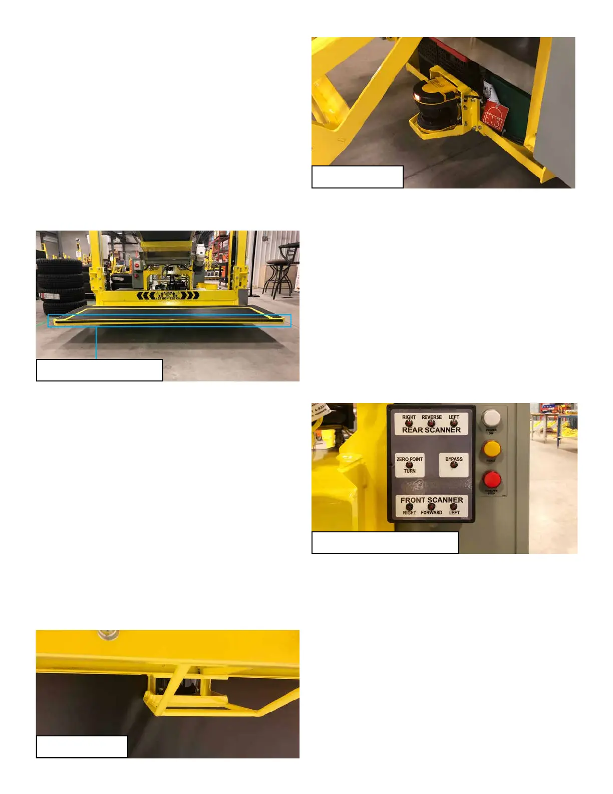
The Destu-it machine may use a forward sensing edge switch to
stop forward travel if the machine impacts an object. The machine
will stop driving forward and the conveyor belts will shut o. The
fault can be cleared by driving the machine backwards for one
foot. The switch is located along the forward edge of the operator
platform. The switch is a 2 wire Normally open switch. It sends
a 24VDC signal to the PLC if activated. There is terminal strip
connector inside the platform box which connects the switch to the
PLC circuits. The switch is fused in the Control Panel.
AREA SCANNERS
There is an option on the Destu-it machine for an area scanner
on the front or rear of the machine or both.
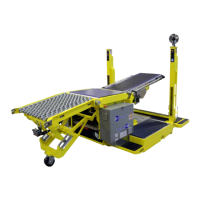
The area scanners are comprised of a few parts. The main body
of the area scanner, which incorporates the actual optical scanner,
is located under the front of the operator platform and on the rear
of the machine base. The scanner head/display for each unit
is found inside an enclosure under the center oor plate in the
base of the machine. On the top of each display/head is the black
memory module. The memory module contains the software for
the scanner and connects to a power/logic output harness. The
scanner body and display are connected with a dedicated cable.
The scanner lens and ledge must be kept clean for the scanner to
function. The lens must only be cleaned with a clean, soft, damp
cloth or a pre-moistened lens cleaning cloth. The area scanner
is an optical device so the lens or ledge may not appear dirty,
but should be cleaned if it senses something that isn’t visibly
apparent.
The area scanners control various operations of the Destu-it. The
scanners have two distinct zones. There is a warning zone and a
stop zone for each scanner. The front and rear zones are dierent
sizes and shapes. The zones are programmed by ELS and
must not be altered. The zones are calibrated to ignore machine
components always within their view such as the cage frame on
the front unit and the support frame for the third conveyor. If a
warning zone is activated, the machine will slow down and steer
away from it automatically. If a stop zone is activated, the machine
will stop driving and the conveyor belts will shut o and/or stop the
platform from lowering.
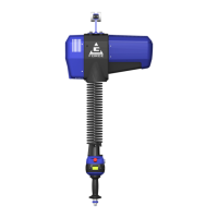
A scanner LED box is installed on the Control panel. The LEDs
on the box indicate which area the scanner is detecting an object
and whether it is in the warning zone (LED ashes) or stop zone
(LED is solid). The scanner display box will also activate a Zero
Point Turn or Bypass LED which recommends the action needed
to move the machine away from the object.
The scanner body should never be adjusted or moved without
authorization rst. The scanner bodies are precisely positioned
and should never need adjustment.
Area Scanner Bypass
The scanners can be temporarily bypassed by the operator if
the machine is in a position where it cannot move or the platform
won’t go down. Using the switches on either side of the front
conveyor, the operator can temporarily bypass the scanners to
move the machine. The operator can only move in one direction
(zero turn, forward or reverse) until the scanners re-activate.
Once the operator stops the machine travel, the area scanners
work again. If required, they can be bypassed again to perform
another movement of the machine, until the machine is clear of the
obstruction. This procedure can be done in either AC or DC mode.
Front Area Scanner
Scanner LED Box (Control Panel)
Rear Area Scanner
Front Sensing Edge Switch