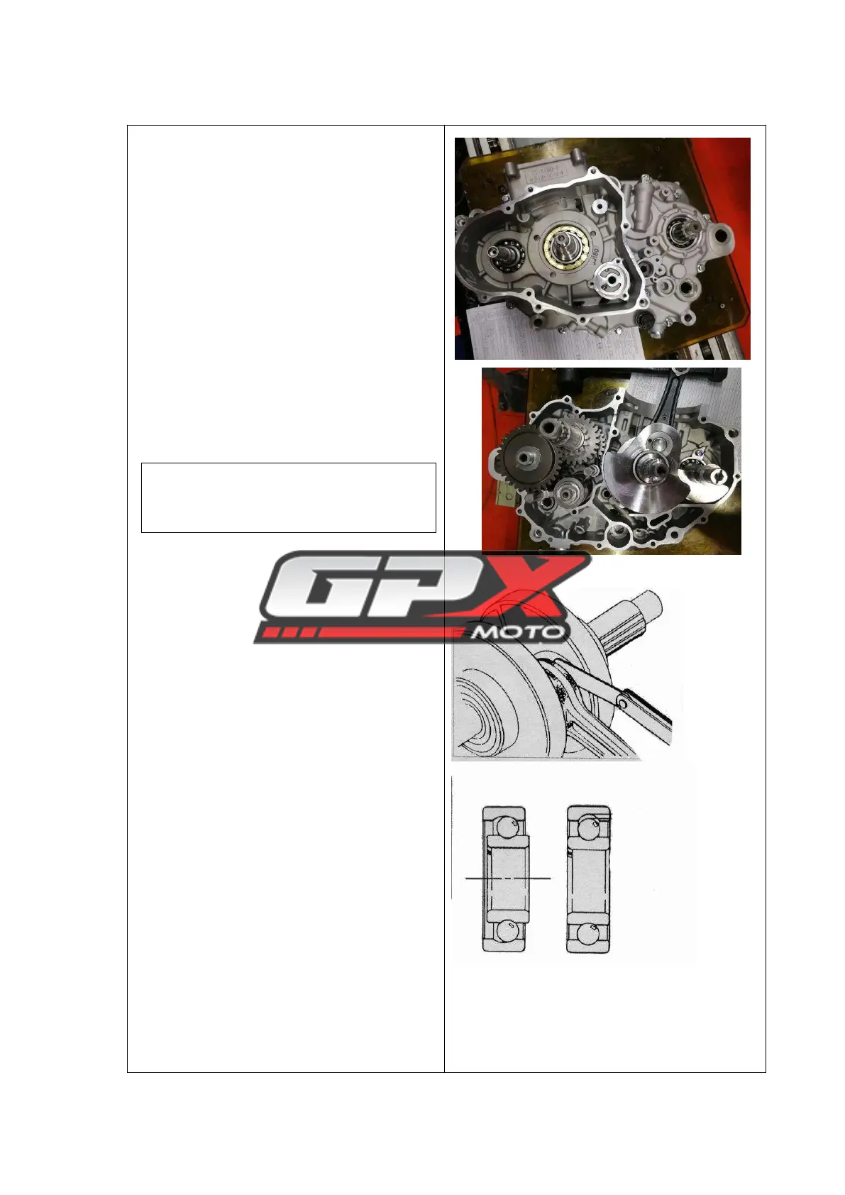
Disassembly of the crankcase
1. Place the left crankcase of the engine
upwards;
2. Remove the fastening screws of 3 bolts
M6 ×70, 3 bolts M6×65 and 6 bolts M6 × 45,
separate the left crankcase from the right
crankcase, and remove the 2 positioning pins.
Removal of crankshaft/balance
shaft/main and auxiliary shafts
Take out the crankshaft assembly, balance
shaft, shift fork shaft, shift fork, shift drum, and
main and countershaft components from the box.
Notice:
When taking out the main and auxiliary
shaft assemblies, make sure that no parts
are left behind .
crankshaft inspection
Use a thickness gauge to measure the
backlash at the big end of the connecting rod.
Service limit: 0.7 mm
Inspection of left and right case bearings
1. Check whether all the bearings of the left
and right boxes rotate flexibly; if the rotation is
not flexible or there is a phenomenon of hairpin,
the bearings of the same type should be replaced