Pressure
Control
WARNING
INJECTION
HAZARD
T
o reduce the risk of serious injury
,
whenever you are instructed to relieve
pressure, follow the
Pressure Relief
Procedure
on page 17.
NOTE:
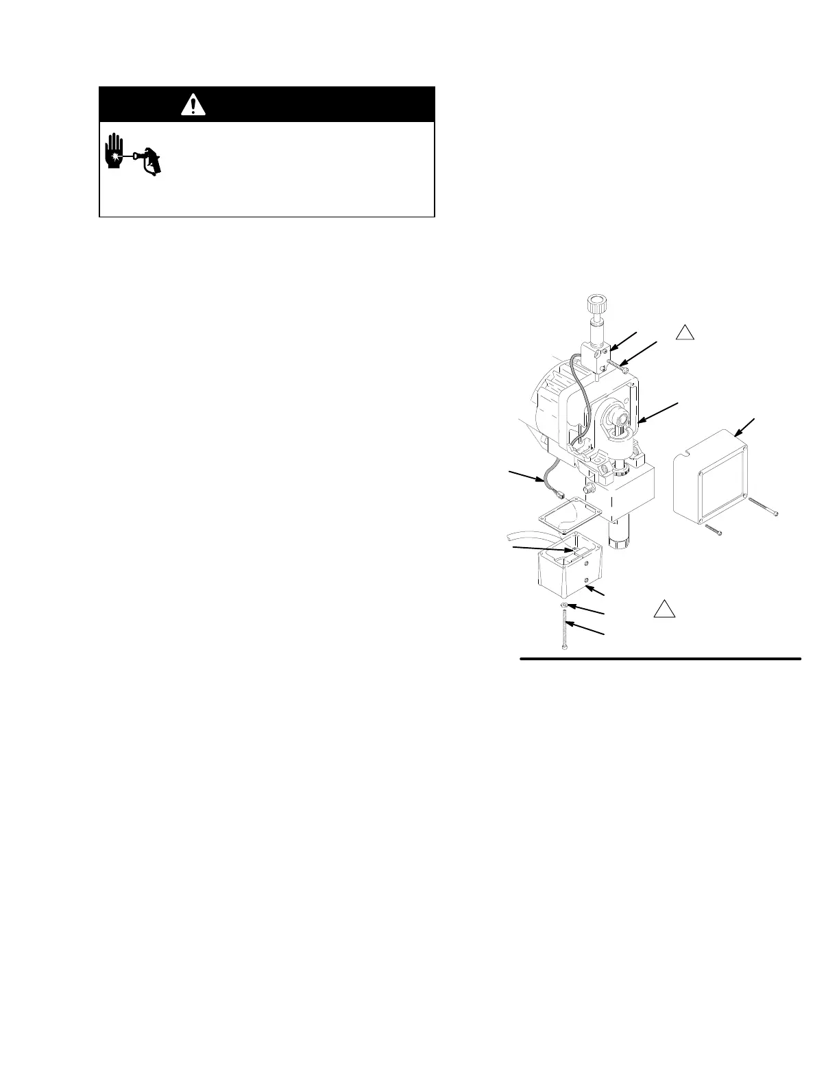
See Fig. 10 for this procedure.
NOTE:
The pressure control (25) cannot be repaired
or adjusted. If it has malfunctioned, replace it.
1.
Remove the front cover (9). Remove the screws
(65) and lock washers (37). Lower the junction box
(63).
2.
Disconnect the harness connector (A) from the
control module inside the box (63).
3.
Remove the screws (24). Pull forward on the
pressure adjusting knob and tip the pressure
control (25) forward and up to detach it from the
drive housing (6).
4.
Guide the harness (A) through the pinion housing
and drive housing and remove the pressure con
-
trol.
5.
Guide the harness of the new pressure control
through the drive housing and pinion housing
passages.
6.
Install the new pressure control. T
ip the pressure
control down and back into the drive housing (6).
Do not pinch or damage the harness (A).
7.
Loosely install the screws (24) and then torque
them to 21 in–lb (2.4 N.m).
8.
Install the front cover (9). Connect the harness (A)
to the control module leads (B).
9.
Install the junction box. Be sure no leads are
pinched against the mounting face of the pinion
housing.
25
24
63
37
A
9
6
Torque
to
21 in–lb (2.4 N.m)
Fig.
10
65
B
06924