308-550 7
Installation
Mountings
CAUTION
The pump exhaust air may contain contaminants.
V
entilate to a remote area if the contaminants
could af
fect your fluid supply
. See
Air Exhaust
Ventilation
on page 10.
Be sure the mounting surface can support the
weight of the pump, hoses, and accessories, as
well as the stress caused during operation.
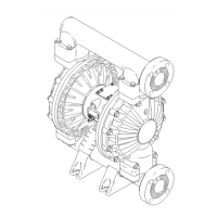
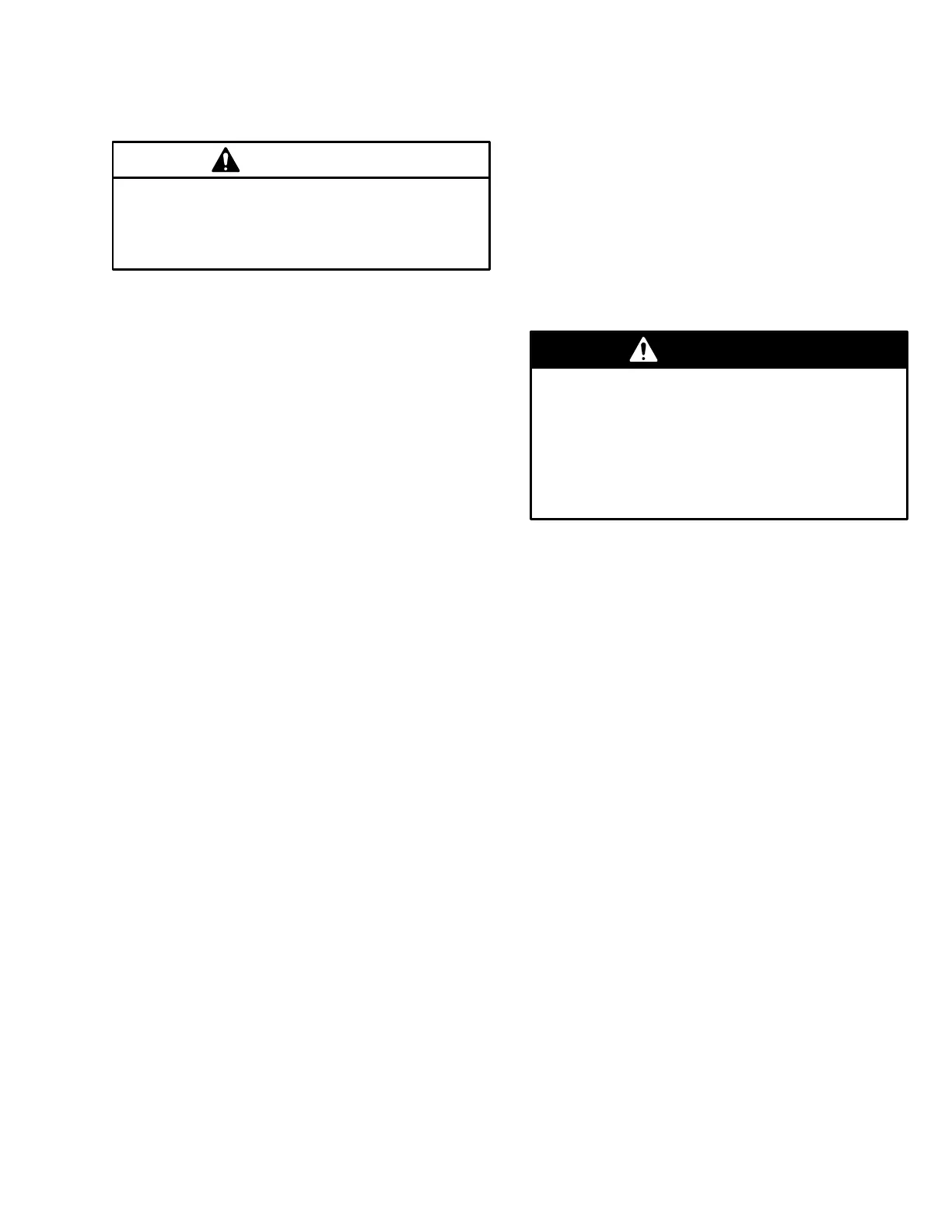
For all mountings, be sure the pump is bolted
directly to the mounting surface.
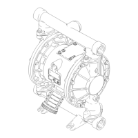
For ease of operation and service, mount the pump
so the air valve cover (2), air inlet, and fluid inlet
and outlet ports are easily accessible.
Rubber Foot Mounting Kit 236–452 is available to
reduce noise and vibration during operation.
Fluid Suction Line
1. The
pump fluid inlet (R) is a 2” raised face flange.
Refer to
Flange Connections
on page 8.
2.
If the fluid inlet pressure to the pump is more than
25% of the outlet working pressure, the ball check
valves will not close fast enough, resulting in
inef
ficient pump operation.
3.
At inlet fluid pressures greater than 15 psi
(0.1 MPa, 1 bar), diaphragm life will be shortened.
4.
See the
T
echnical Data
on page 30 for maximum
suction lift (wet and dry).
Fluid Outlet Line
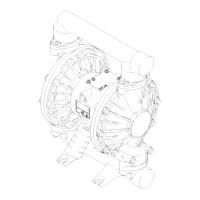
WARNING
A
fluid drain valve (J) is required to relieve pres
-
sure in the hose if it is plugged. The drain valve
reduces the risk of serious injury
, including splash
-
ing in the eyes or on the skin, or contamination
from hazardous fluids when relieving pressure.
Install the valve close to the pump fluid outlet. See
Fig. 2.
1.
The pump fluid outlet (S) is a 2” raised face flange.
Refer to
Flange Connections
on page 8.
2.
Install a fluid drain valve (J) near the fluid outlet.
See the
WARNING
above.
3.
Install a shutoff valve (K) in the fluid outlet line.